Engineering overview
60 GHz Presence Detection: How to Design Detection Coverage with the TAKEX MMW-3.
A passive infrared (PIR) detector cannot detect a person who remains completely still. This is not a limitation of a particular model, nor is it something that can be corrected by adjusting sensitivity — it is inherent to the detection principle itself. The pyroelectric sensor responds to changes in thermal radiation over time. Once a person stops moving, that change disappears, and within a few seconds, the person effectively disappears from the PIR detector’s view.
For lighting automation, this is a minor limitation. For security applications, it is not. An intruder who stops moving, a person who loses consciousness, or a patient who falls and remains motionless all fall directly into the PIR detector’s blind spot — and no sensitivity adjustment can eliminate it.
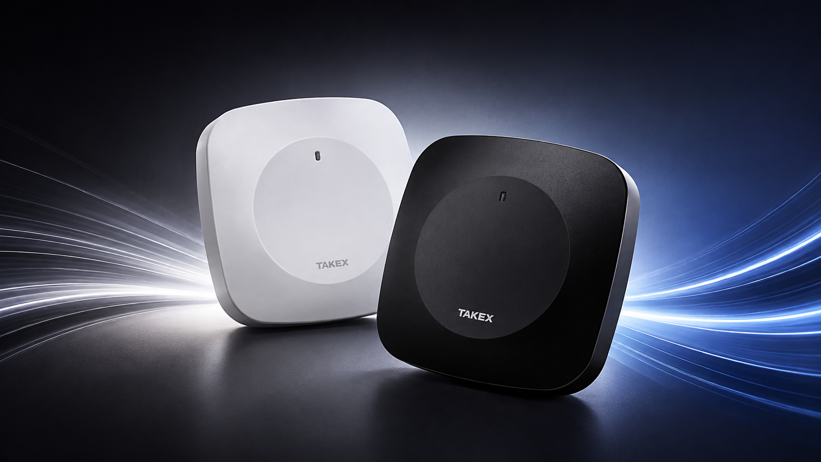
Millimeter-wave presence detectors are designed specifically to address this gap. The TAKEX MMW-3 is one such detector. In the sections that follow, we look at how to incorporate it into a system design: what configuration options it provides, how to calculate detection coverage, what to consider when selecting a mounting location, and which parameters should be verified on site.
1. What 60 GHz Enables
At 60 GHz, the radar wavelength is approximately 5 mm. This is what makes millimeter-scale motion detectable: movements of just a few millimeters — including chest movement caused by breathing and subtle shifts in body position — produce a measurable phase response. As a result, the sensor can continue to detect a person who appears stationary, after a PIR detector would have already lost detection.
The same operating principle also brings several practical advantages.
Independent of ambient light and air temperature.
Radar detection does not rely on thermal contrast, so high ambient temperatures do not reduce its detection coverage in the way they can with PIR detectors. Changes in lighting conditions, a floodlight switching on, or a patch of direct sunlight on the floor do not affect the detection principle.
No optical components to maintain.
There is no Fresnel lens to collect dust, no optical window that requires routine cleaning, and no loss of detection performance caused by contamination of an optical surface.
Very low radiated power.
The specified maximum mean equivalent isotropically radiated power (EIRP) is 6.0 dBm, or approximately 4 mW. For comparison, this is roughly two orders of magnitude below the typical transmit power of a mobile phone. The device is certified to FCC Part 15 Class B and RED 2014/53/EU, and carries UKCA and RCM markings. In practical terms, the RF compliance aspects are already addressed at the product level rather than becoming a separate issue for the integrator to resolve.
Low power consumption and a wide supply voltage range.
The detector operates from 9–28 V DC with no polarity requirement and draws up to 40 mA. It can therefore be powered from a standard security-system power supply. The power source must comply with IEC 60950-1 SELV/LPS or IEC 62368-1 ES1/PS2 requirements — standard provisions for power supplies used in security systems.
2. Outputs
The device provides three relay outputs:
- Alarm — selectable N.C./N.O. dry contact; remains active continuously while detection is present, with a minimum activation time of 2 seconds; rated 30 V, 0.2 A.
- Trouble — N.C. dry contact; activates in the event of low supply voltage or a sensor fault.
- Tamper — N.C. dry contact; activates when the cover is removed; rated 30 V, 0.1 A.
Three independent status outputs on a compact indoor detector provide a more complete interface than is typical for this class of device. The minimum 2-second activation time ensures reliable detection by the control panel regardless of its polling interval. One architectural point is important at the design stage: the detector reports zone status, so any higher-level analytics — such as event counting or correlation between rooms — must be implemented upstream. The number of zones that need to be distinguished therefore determines the number of panel inputs required.
3. Configuration Tools
For a detector of this size, the range of configuration options is quite comprehensive.
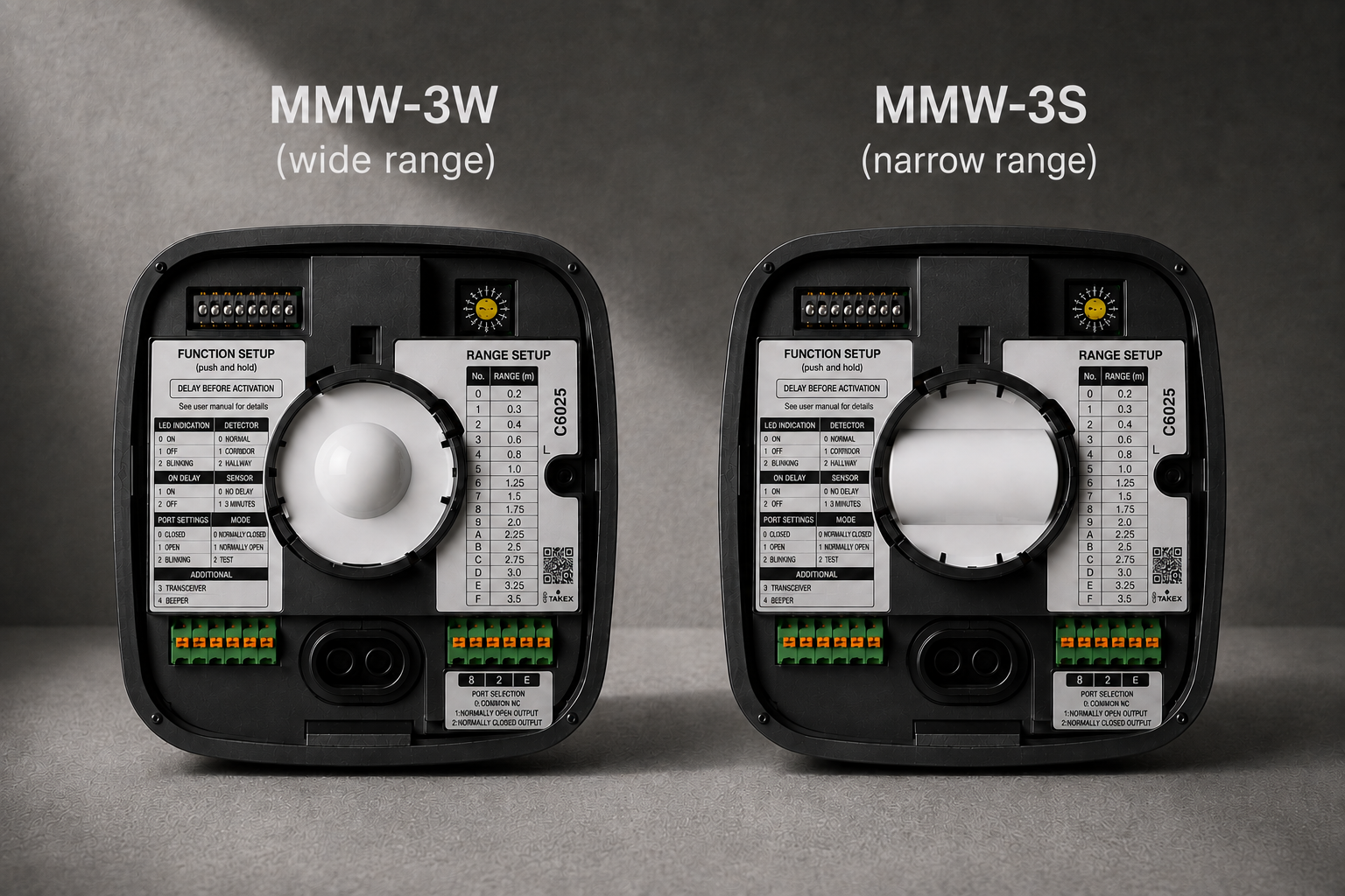
Sixteen detection range settings. Selected using a rotary switch:
| Position | 0 | 1 | 2 | 3 | 4 | 5 | 6 | 7 |
|---|---|---|---|---|---|---|---|---|
| Detection range, m | 0.2 | 0.3 | 0.4 | 0.6 | 0.8 | 1.0 | 1.25 | 1.5 |
| Position | 8 | 9 | A | B | C | D | E | F |
|---|---|---|---|---|---|---|---|---|
| Detection range, m | 1.75 | 2.0 | 2.25 | 2.5 | 2.75 | 3.0 | 3.25 | 3.5 |
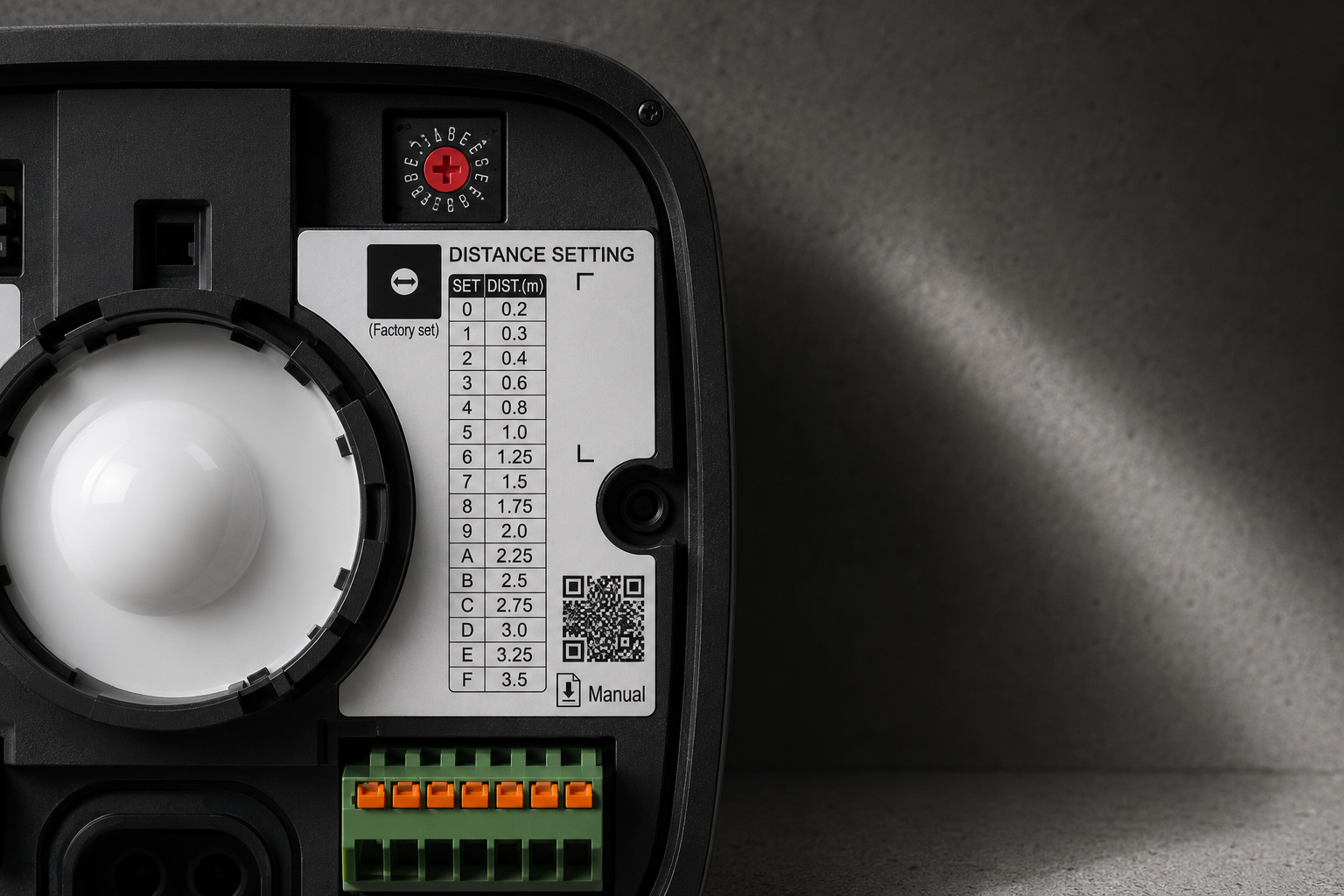
The scale is deliberately non-linear. At close range, the adjustment step is 0.1–0.2 m, where even 10 cm can determine whether the detector responds to a nearby hand or to a person walking past the protected area. At typical security detection distances, the step increases to 0.25 m — fine enough to exclude a specific source of unwanted detection without sacrificing useful coverage. Position 0 (0.2 m) provides the specified touchless mode, so no separate mode selector is required.
- 90° lens rotation on the MMW-3W. The W version has an elongated detection pattern, and the lens can be rotated and locked in either of two orientations: horizontal (the factory-default “Landscape” position) or vertical (“Portrait”). In practical terms, the same detector can cover either a wide passageway or a tall, narrow space without requiring a different model. On the MMW-3S, the lens orientation is fixed.
- Two versions for different applications. The MMW-3W provides a wide detection pattern for rooms and passageways. The MMW-3S provides a narrow pattern for doorways, cabins, or other specific detection points.
- On-delay timer: Off / 10 s / 15 min / 30 min. The 10-second setting acts as a filter for brief transient events. The 15- and 30-minute settings, by contrast, allow the detector to signal prolonged presence.
- Standard / Low sensitivity selector — the first adjustment to consider if nuisance alarms occur after installation.
- Memory indication. When enabled, the yellow indicator flashes for 3 minutes following a detection event, then remains steadily lit for 47 minutes before turning off. A new detection event restarts the steady-on period, providing approximately one hour of local event memory. During a site inspection, this allows personnel to see whether presence has been detected in the room within the past hour without having to check the control panel.
- Buzzer — provides local audible indication of detection, particularly useful during commissioning and functional testing.
4. How to Calculate Detection Coverage
The four mounting combinations produce the following approximate detection areas:
| Model and mounting | Footprint (top view) | Depth (side view) |
|---|---|---|
| MMW-3W, ceiling-mounted | ≈ 4 × 2 m | up to 3.5 m downward |
| MMW-3W, wall-mounted | ±2 m over 3.5 m | up to 2 m |
| MMW-3S, ceiling-mounted | ≈ 2 × 2 m | up to 3.5 m downward |
| MMW-3S, wall-mounted | ±1 m over 3.5 m | up to 2 m |
The dimensions shown are based on typical mounting heights: 2.5 m for ceiling mounting and 1.5 m for wall mounting.
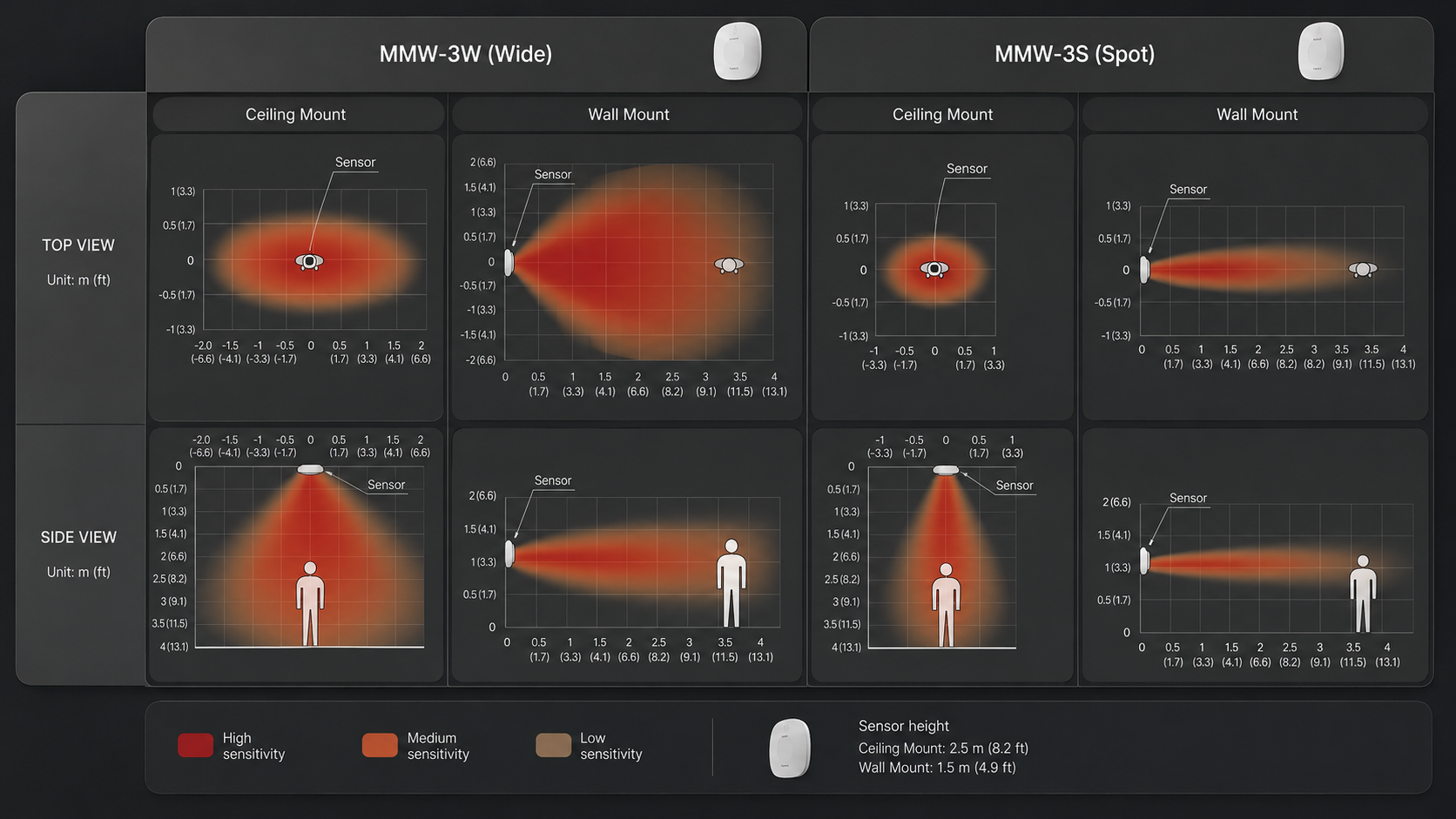
For wall-mounted installations, this corresponds to an approximate coverage angle of 60° for the MMW-3W and 30° for the MMW-3S.
There are two points to consider when laying out the detectors.
The MMW-3W detection pattern is elongated rather than symmetrical — approximately 4 m × 2 m. This is why the lens can be rotated by 90°: the orientation of the detection pattern can be matched to the geometry of the space.
The 3.5 m detection range is measured along the detection axis. With ceiling mounting, this axis points downward, so the ceiling height consumes part of the available range, while the resulting floor-level footprint corresponds to the dimensions shown in the table above. Coverage calculations should therefore be based on the footprint dimensions, not on the detection range as a radius; otherwise, the required number of detectors for a given space will be underestimated.
One more point: with ceiling-mounted MMW-3W detectors, sensitivity gradually decreases toward the edge of the detection pattern. The footprint boundary should therefore be treated as a transition region rather than a hard line. When laying out multiple detectors, base the design on the reliable portion of the detection pattern and verify the actual boundaries on site during commissioning.
5. Prolonged Presence Detection: How to Configure It Reliably
The 15- and 30-minute on-delay settings cover scenarios that would otherwise typically require additional logic at the control panel: a person remaining in a restricted area longer than permitted, an unusually long stay in a restroom or fitting room, or a person failing to leave an area within the expected time.
The operating logic is straightforward: the output is activated only when the sensor continuously detects a target for longer than the configured delay. If the target is lost, the timer resets and starts again from zero when detection resumes.
What this means in practice. The timer measures continuous presence, not cumulative time spent in the detection zone. For most security applications, this is the desired behavior: a person who leaves the area and later returns should not accumulate presence time across separate visits. The design implication, however, is that for a 30-minute delay, detection must remain stable throughout the entire 30-minute period.
Practical recommendations:
- Choose the delay with some margin in favor of earlier detection. If the allowable dwell time is 30 minutes, it is generally better to use the 15-minute setting and add confirmation logic at the control panel than to rely on a single uninterrupted 30-minute timing cycle.
- Validate the function on site, with an actual stationary person under real operating conditions, for the full selected delay period. This is the only reliable way to confirm that the chosen mounting location maintains stable target detection throughout the required interval.
- Where prolonged presence detection is a critical project requirement, consider adding an independent source of confirmation — such as door status monitoring, passage counting, or a second detector.
6. Selecting the Mounting Location
Radar responds to a different set of environmental factors than PIR, so mounting locations proven effective for infrared detectors should be reassessed rather than carried over by default. The list of factors that affect performance is short and specific.
- Metal surfaces in or near the detection area can produce reflections that lead to nuisance alarms. With a ceiling-mounted MMW-3W, this can include metal objects located outside the nominal detection pattern. Large metal structures — such as shelving, roller shutters, and cabinets — should therefore be kept out of the detector’s field of view during the layout stage rather than compensated for later through sensitivity or range adjustments.
- Glass and transparent plastic within the detection area attenuate the radar signal. A glass partition should not be treated as a barrier to the radar, but as an attenuating material; as a result, the area beyond it should be considered neither reliably excluded from detection nor reliably covered.
- Moving objects — such as plants, hanging fabric, fans, or flowing water — can also trigger detection. For a sensor designed to detect micro-movements, the motion of leaves can produce a detectable response similar to the small movements the sensor is intended to capture. The practical solution is to adjust the detection range: unwanted sources of movement can be excluded from the detection area using one of the sixteen range settings.
- Structural vibration — mount the detector only on a stable, vibration-free surface.
- Electromagnetic environment. The consideration works both ways: the detector may not operate correctly near equipment that generates strong electric or magnetic fields, and such equipment may in turn be affected by the detector’s emissions. This is generally not a concern in typical office or retail environments. In plant rooms, mechanical rooms, and server rooms, however, potential interference in both directions should be checked before commissioning. Installation near medical equipment requires particular attention.
If nuisance alarms occur after commissioning, troubleshoot them in this order: first remove the source of unwanted movement or exclude it from the detection area; then adjust the detection range; and only as a last resort switch the sensitivity to “Low.” The order matters: whenever sensitivity is reduced, verify that the detector can still maintain reliable detection of a stationary target. As with any detector, there is a trade-off between sensitivity and immunity to nuisance alarms.
Concealed Mounting
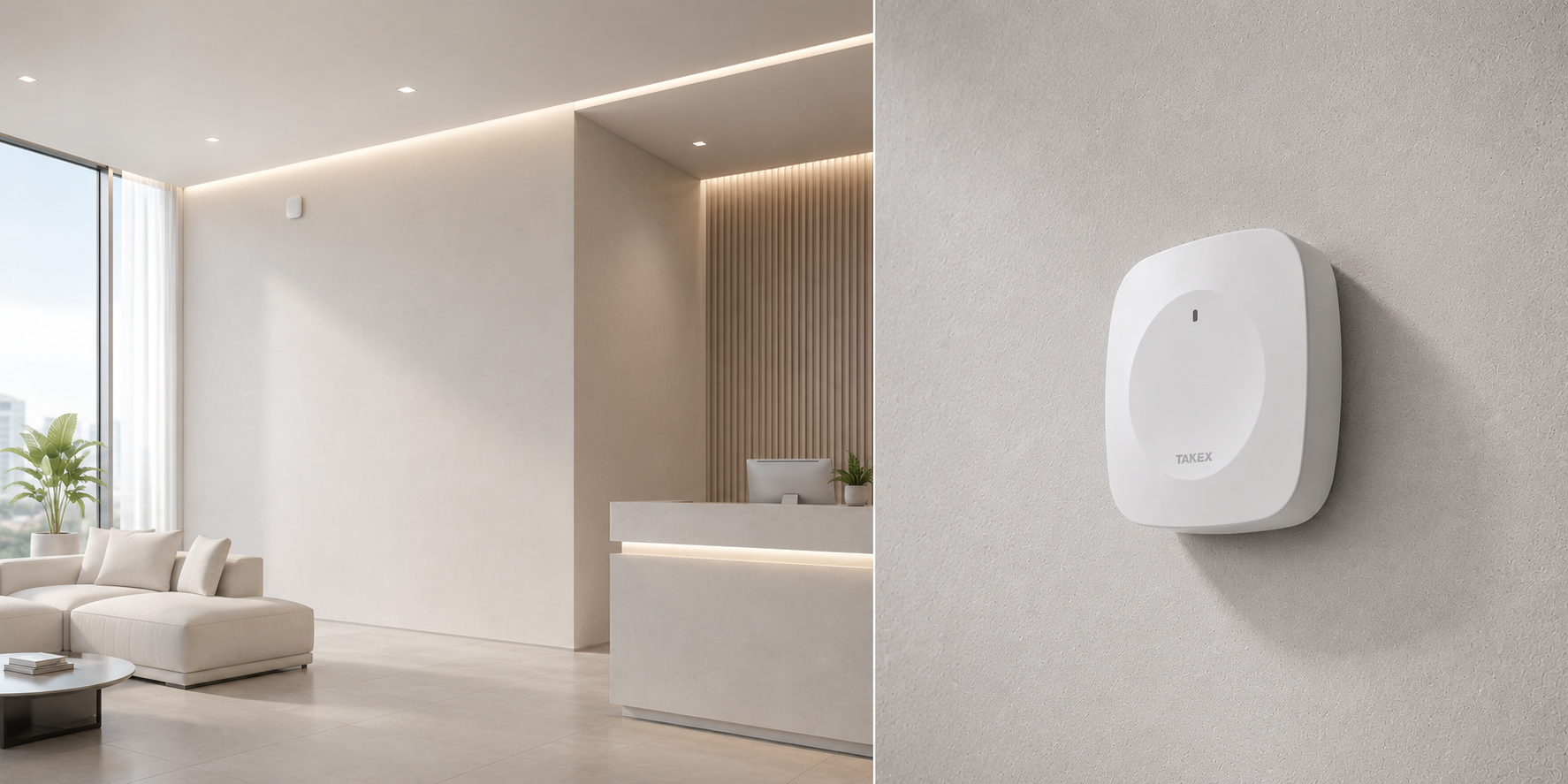
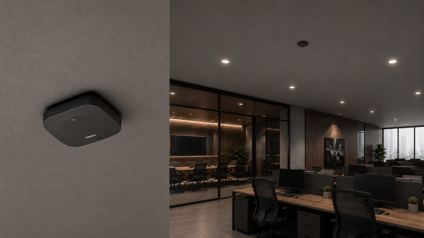
Radar signals can pass through non-conductive materials, enabling an installation option that infrared detectors do not offer: the detector can be concealed above a suspended ceiling or behind a drywall partition, preserving a clean, unobtrusive interior. In museum applications, the same principle can be used to monitor the approach to an individual exhibit — the detector can be concealed behind a canvas or an adjacent panel, remaining completely out of sight in the gallery.
There is one critical condition: there must be no conductive layers between the detector and the detection area. Metal framing, foil-backed drywall, foil-faced mineral wool, and metal suspended ceilings block the radar signal. Standard drywall, wood, fabric, and canvas do not prevent the signal from passing through, but every layer introduces some attenuation. The detection range behind the covering material must therefore be established on site rather than assumed from the range achieved with the detector mounted in the open.
For concealed installations, always test with a stationary person. Successful detection of someone walking through the area confirms only that the radar signal is getting through; maintaining detection of a person standing still shows whether enough signal margin remains to detect micro-movements. That is the capability the detector is being installed for, and it is the first to degrade as signal attenuation increases.
There are two practical implications to plan for in advance. All settings — detection range, timer, and contact type — must be configured before the detector is concealed, so the required operating mode should be defined during the design stage rather than adjusted after handover. Service access should also be provided, either through an access hatch or a removable panel. Without it, routine testing is limited to observing the response at the control panel, and the tamper circuit may be triggered whenever work is carried out in the ceiling void.
7. Multiple Detectors in a Single Space
The MMW-3 does not provide channel synchronization between adjacent detectors, so the rule is straightforward: detectors facing each other should not have overlapping detection patterns. Set the detection range of each unit so that the detectors do not interfere with one another.
In practical terms, the detection patterns should be designed to meet rather than overlap. This is where the sixteen range settings are particularly useful: they generally provide enough adjustment to divide the space between detectors with the required precision. For ceiling-mounted arrays with detectors aimed vertically downward in parallel, there is no explicit restriction on overlap, but closely spaced configurations should be verified on site. This is a quick check that can be performed during commissioning.
One additional point to be aware of: the Spot version may fail to detect a person in the presence of a continuous-wave signal at the same transmit frequency. This is a known characteristic of radar-based sensors and is documented in the test results under ETSI TS 103 361.
The engineering conclusion is standard and not specific to the MMW-3. Where the threat model includes a knowledgeable and deliberate intruder, no single sensor — radar, infrared, or ultrasonic — should be relied upon as the sole means of detection. The detection layer should use at least two technologies based on different physical principles, with their alarm signals correlated at the control panel or PSIM level. For sites with a conventional threat profile, this consideration is generally not relevant.
A related point from the same standard: the test criterion is expressed in terms of positional error — ±0.25 m at a range of 1 m, with a Detection Rate above 95%. It is important to understand that this is an acceptance criterion for the immunity-to-interference test, not a specified probability of detection in a real-world installation. What it does reveal, however, is something interesting: internally, the sensor determines target range with a resolution of approximately 25 cm. In other words, the signal processing taking place inside the device is considerably more sophisticated than the simple relay output might suggest.
8. Power and Wiring
The power terminals, together with the spare terminal, provide internal continuity, allowing the power line to be daisy-chained through multiple detectors. The standard wiring arrangement connects the detection outputs in series to a single control panel input, which is convenient when several detectors are intended to operate as one logical zone. If individual detector identification is required, connect each detector to a separate panel input.
Maximum cable length using solid conductors:
| Conductor | 12 V DC | 24 V DC |
|---|---|---|
| Ø0.65 mm (AWG 24, 0.2 mm²) | 350 m | 1,800 m |
| Ø0.9 mm | 650 m | 3,400 m |
| Ø1.2 mm (AWG 16, 1.0 mm²) | 1,200 m | 6,100 m |
When multiple detectors are daisy-chained on the same power line, the maximum cable length shown above should be divided by the number of detectors. In effect, the figures represent a shared power budget expressed as cable length: eight detectors on Ø0.65 mm conductors allow approximately 44 m at 12 V DC or 225 m at 24 V DC. Using 24 V DC increases the available wiring distance by roughly a factor of five, which is worth accounting for early when designing distributed installations.
A few practical details that save time during installation:
- Cable routed through the knockout opening must not exceed Ø6 mm; otherwise, it may interfere with the main unit when the detector is assembled.
- Strip conductors to 8 mm. The terminals are screwless and feature push-button release.
- Seal any unused openings — not only to prevent moisture ingress, but also to keep insects out.
- Install the base with the arrow pointing upward, using the two supplied Φ4 × 20 screws, and secure it to a solid mounting surface.
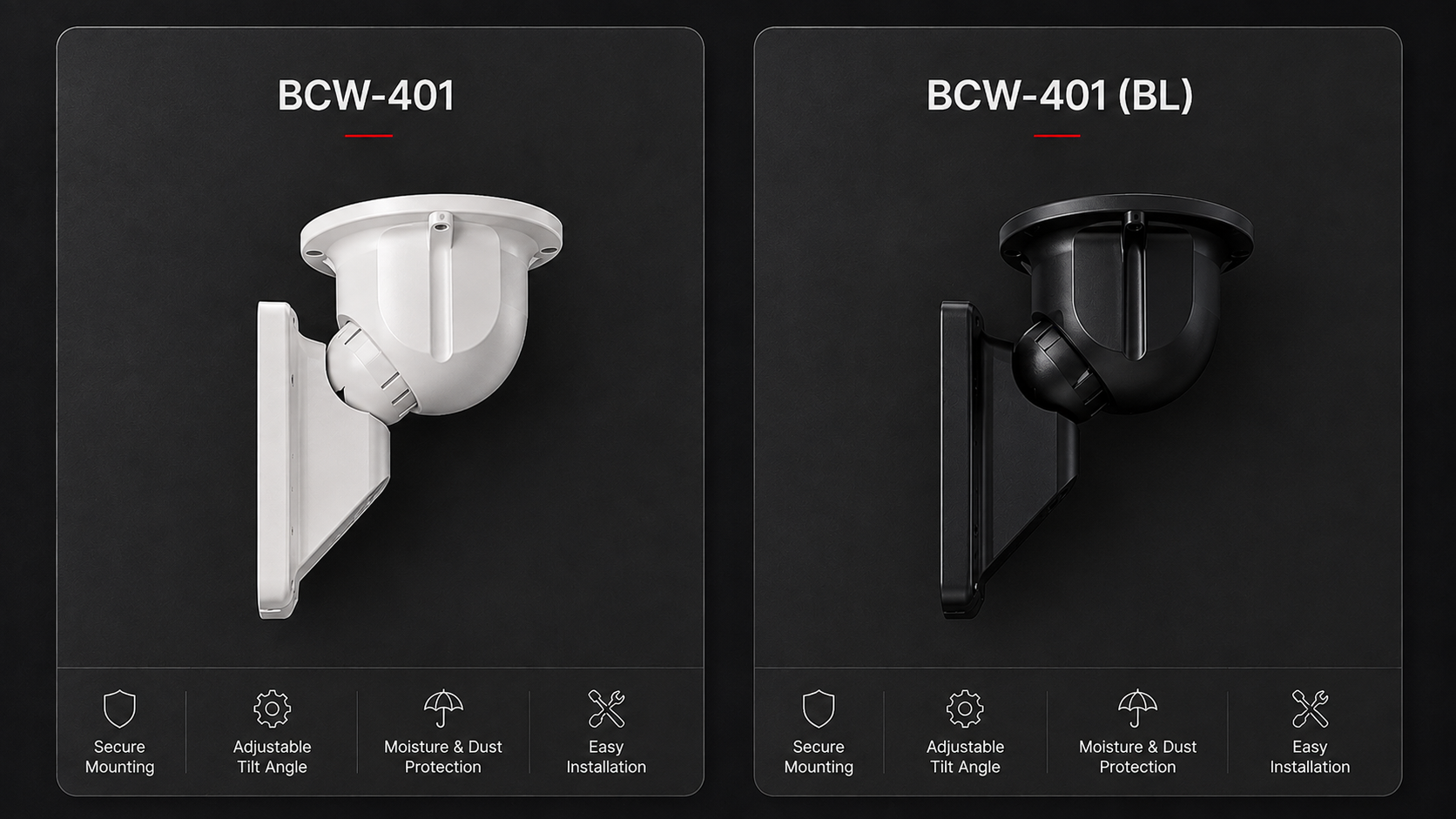
- For angled installation, the BCW-401 mounting bracket is available in both white and black.
The minimum separation distance from a person required for RF exposure compliance is 17 cm under CE requirements and 20 cm under FCC requirements. With normal ceiling- or wall-mounted installations, these distances are met automatically. They only require specific consideration in touchless applications, where the detector is installed within direct reach of the user’s hand.
9. Commissioning and Maintenance
The commissioning check should follow this sequence: verify the indicator at power-up; enter the detection area and confirm that the indicator turns red; verify that the alarm signal is received by the control panel; remove the cover and confirm tamper operation; then reinstall the cover. Once testing is complete, disable the indicator and buzzer if they are not required during normal operation.
The recommended interval for functional testing is once a week. This is standard practice for security devices: periodic functional checks are part of normal security system maintenance regardless of the sensing technology used. The Memory function makes these checks considerably easier by indicating whether detection has occurred within the past hour, allowing some checks to be completed visually during routine inspection rounds.
One additional point to include in the maintenance plan is that the environment can change over time. A new shelving unit, a relocated partition, or a revised retail floor layout can all affect the detection area. Retesting after any significant change to the space is therefore better practice than relying on a calendar-based inspection interval alone.
10. Where the MMW-3 Is Most Effective
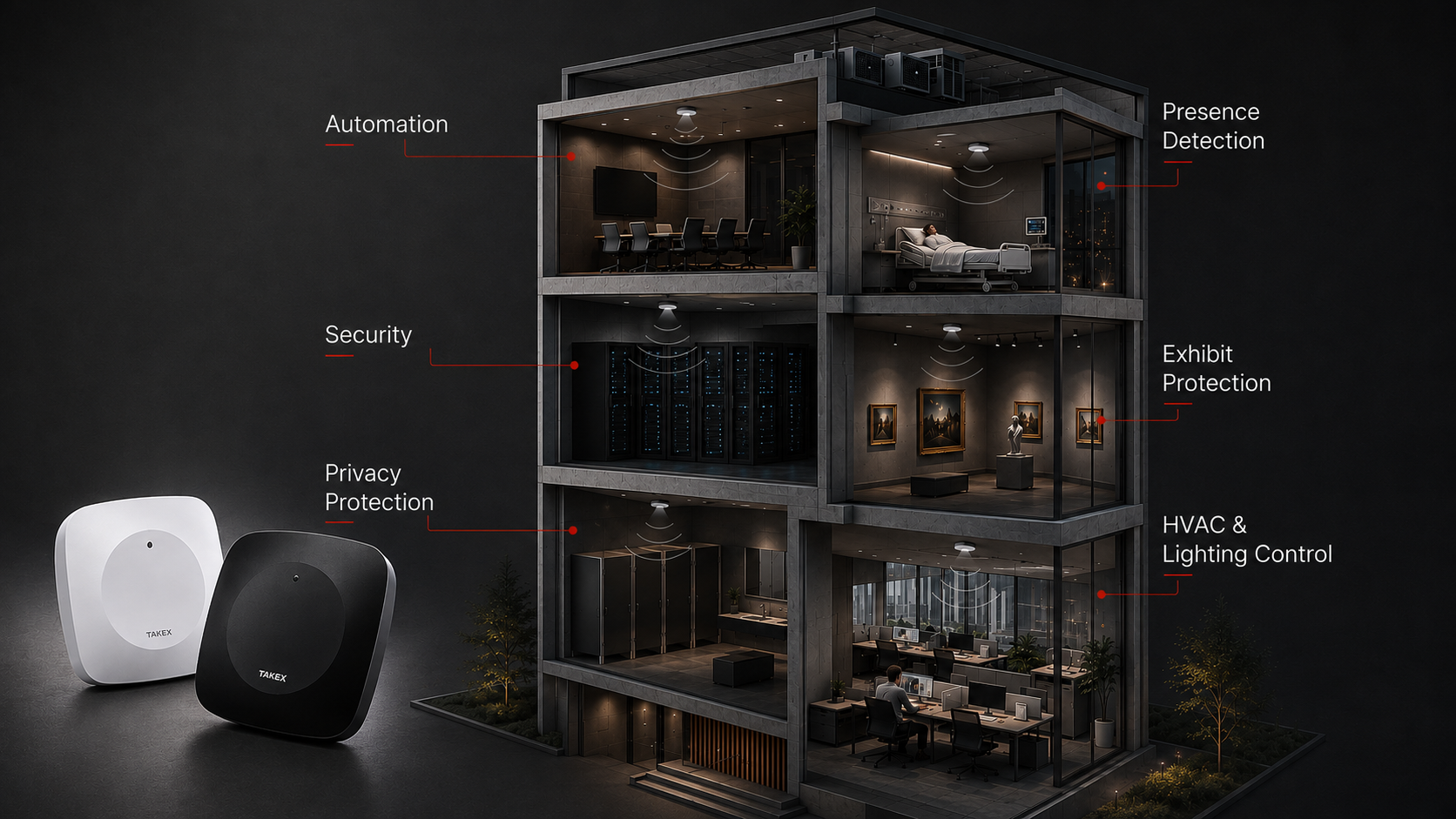
Applications where the MMW-3 provides capabilities that PIR cannot:
- Monitoring spaces where people may remain stationary — lounges, patient rooms, holding cells, booths, server rooms, and meeting rooms;
- monitoring approach to exhibits in museums and galleries — a specific application discussed in more detail below;
- detecting prolonged presence in restricted-access areas using the on-delay timer;
- spaces with challenging thermal conditions where PIR detection becomes less reliable — hot industrial areas, zones with air curtains, and environments subject to rapid temperature changes;
- locations where video surveillance is undesirable for privacy reasons, but presence still needs to be detected;
- interiors and exhibition spaces where detection equipment should remain out of sight: the detector can be concealed above a suspended ceiling or behind a partition made of non-conductive material;
- touchless control applications — doors, lighting, and equipment in areas with specific hygiene requirements.
Exhibit Protection: Why This Application Is a Particularly Good Fit
In a museum setting, the objective is not simply to “detect a person in the gallery,” but to “detect when someone approaches a specific exhibit beyond a defined distance threshold.” A visitor may stand in front of a painting for as long as they wish; an alarm is required only when they cross the boundary beyond which the exhibit may be at risk.
Three capabilities of the MMW-3 work together particularly well in this application.
Fine range adjustment at short distances.
Between 0.3 and 1.0 m, the range settings are spaced in increments of just 0.1–0.2 m. This allows the detection boundary to be set precisely where required by the conservator and adjusted later by a few tens of centimeters without having to redesign the detector layout.
Detection of stationary targets.
A visitor who stops moving in front of a painting may disappear from a PIR detector within seconds — precisely when they are closest to the exhibit. The radar continues to detect their presence, keeping the alarm signal active for as long as the distance threshold remains violated, rather than only when the boundary is crossed.
Visual discretion.
The compact housing, with no visible optics, is unobtrusive in an exhibition space. Where required, the detector can be concealed entirely from view — behind the canvas or behind a nearby panel. With the narrow-pattern MMW-3S, the detection area can be focused on the approach to a single exhibit without unnecessarily extending into adjacent areas.
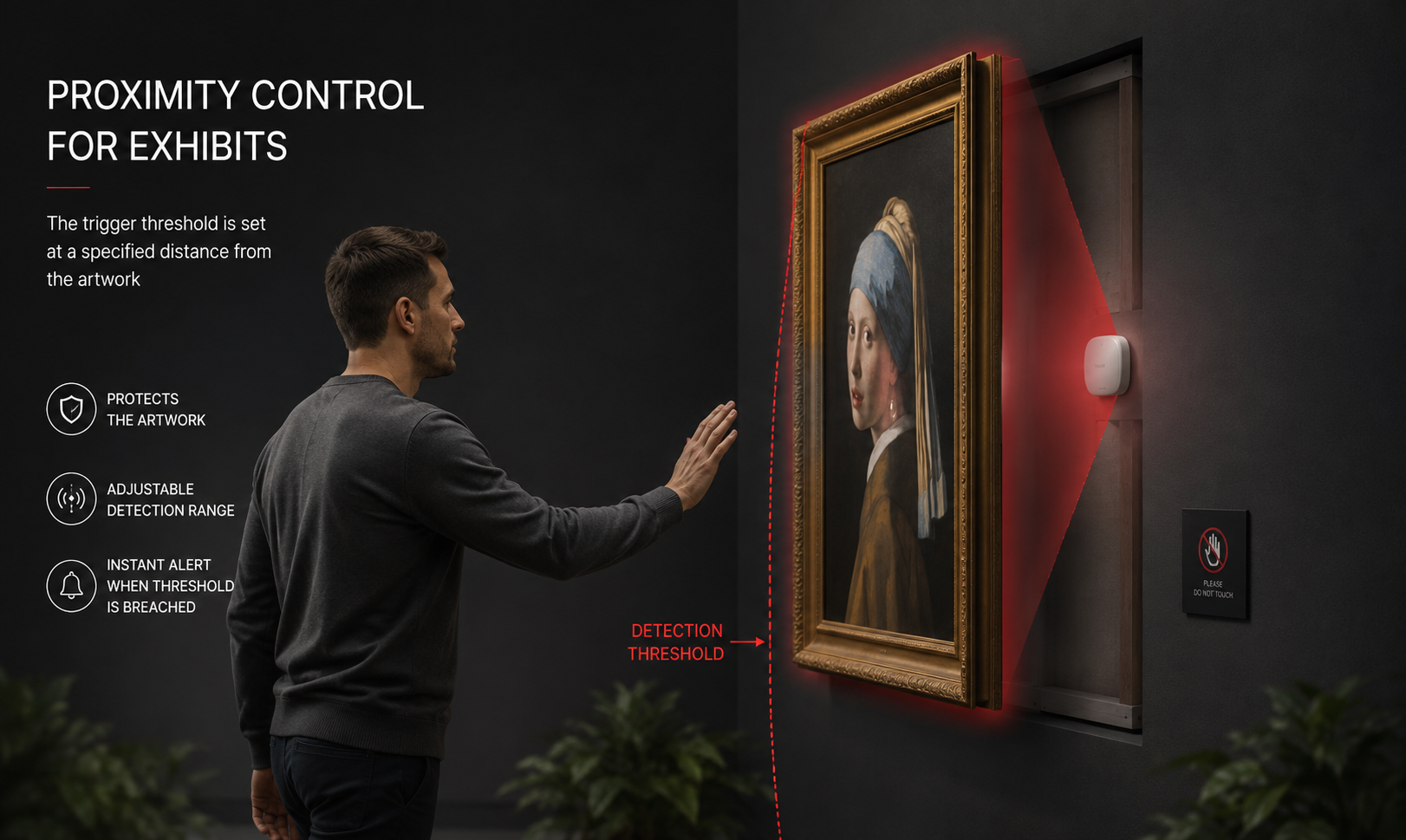
The detection area should be configured for the specific exhibit. The actual detection boundary is measured on site, taking into account metal elements in the frame, the hanging system, and any display case, and the resulting range setting is then recorded as the operating configuration. In galleries with multiple exhibits, the same rules for detection-pattern overlap apply: set the range of adjacent detectors so that they do not interfere with one another.
Design considerations:
- Calculate coverage from the detection-pattern geometry shown in the diagrams, not from the maximum detection range alone; verify the actual boundary on site.
- Keep large metal structures and sources of movement outside the detection area when planning detector locations.
- Where multiple detectors are used, design adjacent detection patterns to meet without overlapping.
- For prolonged-presence detection, verify reliable operation on site over the full selected time interval.
- The specified operating range is −25 to +50 °C under non-condensing conditions. For unheated spaces where condensation may occur, confirm the suitability of the application with the supplier.
- Outdoor use is not specified: the detector is intended for indoor installation only and has no stated IP rating.
11. What to Confirm During the Design Stage
No datasheet can answer every question for a specific installation — this is true of any sensing technology. For the MMW-3, three points are worth confirming during the design stage, and each can be resolved either with the supplier or through a short on-site test:
- The actual detection boundary in the specific installation, with the real ceiling height and surrounding environment taken into account — verify it on site during commissioning.
- Reliable detection of a stationary target at the selected mounting location, where prolonged-presence detection is part of the project requirements.
- Suitability for unheated spaces, where such areas are included in the project.
Both on-site checks are performed during commissioning and take little time. They are considerably less costly than having to reposition detectors after the installation has been completed and handed over.
12. Conclusion
The MMW-3 addresses a specific and relatively narrow requirement: detecting a person who remains stationary within a single room. In this role, it provides a capability that conventional PIR detection cannot reliably provide by design, while remaining unaffected by lighting conditions, ambient temperature, or contamination of optical components.
From an integration standpoint, the MMW-3 is a straightforward device with a surprisingly broad range of local configuration options: two detection patterns, a 90° rotatable lens, sixteen range settings, four timer settings, selectable contact logic, local indication, and event memory. All of this flexibility remains within the detector itself; externally, it simply reports zone status through relay contacts and can therefore be integrated with control panels of virtually any generation.
Engineering conclusion
The main implementation challenge lies not in configuring the detector, but in getting the geometry right: calculating coverage correctly, selecting a location free from problematic reflectors and sources of movement, and separating the detection areas of adjacent detectors. This is primarily a design task, and the quality of that work ultimately determines how well the installed system performs in practice.
FortiSec handles the part of the engineering work that a datasheet cannot: validating the actual coverage against the geometry of the space, determining the required number of detection zones and control-panel inputs for the project specification, performing on-site stationary-target detection tests, and selecting the appropriate detector version and mounting locations for the site layout. If you are designing a system with presence detectors, send us the floor plans and your zone-separation requirements, and we can help turn them into a practical system configuration.