Engineering overview
Camera Housings in Tunnels:
A Review of the Global Proof CSX Series
In a tunnel, a protective camera housing rarely fails in a way that a monitoring system can detect. It does not stop responding, lose power, or generate an error. Instead, image quality gradually degrades until an incident can no longer be identified reliably — or the housing loses its seal integrity after several seasons of scheduled tunnel washing, allowing water inside before the seals have ever been inspected.
Both scenarios have one thing in common: neither looks like an equipment failure. That is also why they are often overlooked during design. The housing appears in the specification as a single line — “outdoor housing, IP66, stainless steel” — and returns to the engineer’s attention two years later, when the operator reports poor image quality at a location that cannot be serviced without closing a traffic lane.
This article examines the Global Proof CSX tunnel series — four models, their design features, and the parameters that determine the choice between them. More importantly, it examines the selection problem itself: what site information is required before a housing is selected, and why, in a tunnel, the question “Which IP rating do we need?” cannot be answered simply by choosing the higher number.
One example illustrates the issue. IP69K, commonly referenced for tunnel housings, verifies resistance to water jets at approximately 80°C and 80–100 bar. IP67 verifies temporary immersion at a depth of 1 m for 30 minutes. These are not adjacent levels on a single scale; they are different tests. Housing selection therefore starts with what actually happens at the site, not with a comparison of IP numbers.
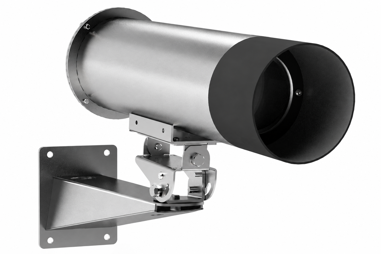
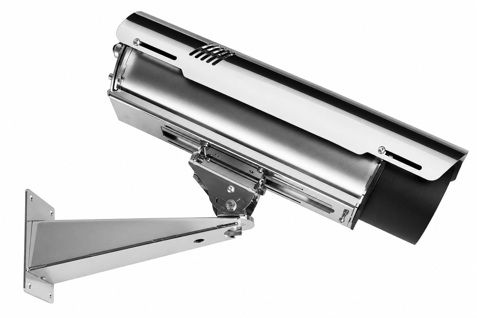
What Actually Loads a Camera Housing in a Tunnel
The phrase “harsh operating conditions” is not useful for engineering design. A better approach is to break the tunnel environment down into individual loads with different failure mechanisms. Each requires a different design response — and each needs to be verified separately.
Airborne contamination. Soot, tire and brake wear particles, and fine dust settle continuously and relatively evenly on the optical window. The key difference from an exposed outdoor installation is not necessarily the amount of contamination, but the absence of rain that would otherwise remove some of it from a vertical glass surface. The result is gradual image degradation without any diagnostic indication from the equipment itself.
High-pressure washing. This is the one external load that acts cyclically and deliberately on the housing seals. An exposed outdoor housing experiences rain, wind, and sunlight, but it is not routinely subjected to a hot water jet at tens of bar. Global Proof explicitly identifies washing as a typical tunnel condition in the description of the CSX610T.
Importantly, the washing operation is not performed for the camera. The tunnel itself is washed — lining, crown, luminaires, and signs — because soot deposits reduce lighting output and sign visibility. The road operator defines the washing interval based on those requirements, and equipment installed within the tunnel cross-section is exposed to the process as a consequence.
The relevant protection rating is therefore not a feature for cleaning the camera. It is a requirement for the housing to withstand someone else’s scheduled maintenance procedure — one that will take place regardless of the CCTV system.
Water from the other direction — flooding. Drainage failure, rainfall beyond the design capacity, or firefighting can create a different exposure scenario. For cameras installed at low points in the longitudinal profile or at low mounting elevations, temporary flooding is not equivalent to pressure washing and is not covered by the same test. In practice, this risk is considered less often than washing, even though it may occur earlier in the system’s life.
Chlorides. Road de-icing chemicals and salt aerosols operate in a confined environment with limited air exchange. Here, specifying “stainless steel” is not enough. The actual stainless-steel grade matters.
Limited service access. Every maintenance intervention carries the cost of a lane closure or a restricted nighttime work window. This moves the question of maintenance frequency from operations into design: a solution requiring regular intervention costs fundamentally more in a tunnel than it does at an easily accessible outdoor site.
Condensation. Temperature gradients around tunnel portals and seasonal changes in humidity can lead to condensation. Heating and internal ventilation manage this risk, but only within defined temperature ranges, as discussed below.
| Load | Failure mechanism | What the housing needs to address | What to verify before specification |
|---|---|---|---|
| Airborne contamination | Image degradation without equipment failure | A means of maintaining optical-window cleanliness | Type of contamination: dry dust or oily deposits |
| High-pressure washing | Loss of seal integrity due to cyclic loading of seals | Verified water-jet resistance | Washing procedure: pressure, temperature, frequency, distance |
| Flooding | Water ingress during temporary flooding | Verified immersion resistance | Mounting elevation relative to the drainage profile |
| Chlorides | Pitting and crevice corrosion | Molybdenum-bearing stainless steel and stainless fasteners | Chemical composition of road treatments and cleaning agents |
| Limited access | Accumulation of deferred maintenance | Design that allows rapid servicing | Cost of lane closure and available maintenance window |
| Condensation | Window fogging; camera operating outside its temperature range | Thermostatically controlled heating and ventilation | Seasonal site temperature profile |
The Optical Window as the System’s Real Service-Life Constraint
Of all the loads above, optical contamination often determines how long the system continues to deliver usable results. The housing itself may remain structurally sound for twenty years; image quality can begin to deteriorate much sooner.
The approach used to keep the optical window clean is therefore one of the first design decisions worth examining.
There are three common approaches, each with its own trade-off.
Mechanical cleaning — a wiper and washer with a fluid reservoir. This provides predictable cleaning performance across a wide range of contamination, including heavy deposits. But it also introduces a motor, pump, reservoir, and consumable fluid at precisely the location that is difficult to access.
Notably, Global Proof does not offer these options in its tunnel series. The wiper and WTP5/WTP25 washer tanks are available for the standard CSX800 industrial series rather than the tunnel models.
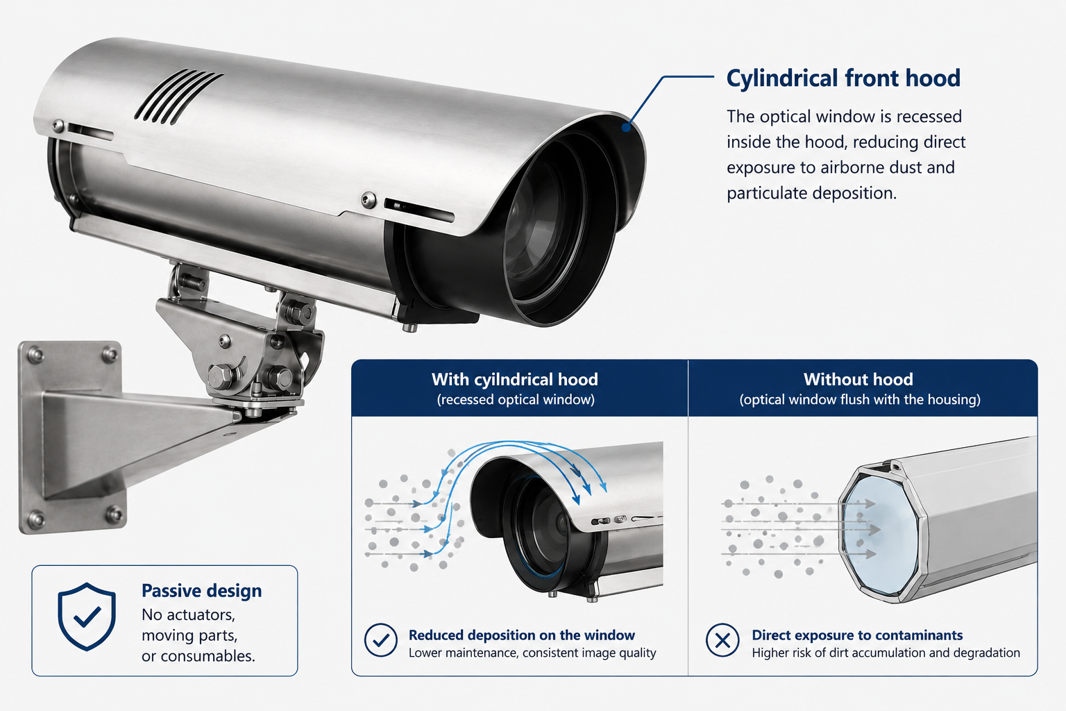
Passive front-end design. All four Global Proof tunnel models — CSX610T, CSX615T POE, CSX810T, and CSX815T POE — use a design the manufacturer calls Clean glass.
This is not a separate device. It is the geometry of the front hood itself: the optical window is recessed within a cylindrical shield, making it substantially more difficult for dust to reach the glass than if the window were flush with the front of the housing. There are no drives, moving parts, or consumables.
The difference from mechanical cleaning is not simply the absence of moving components. The two approaches solve different problems. A wiper removes contamination that has already accumulated. Clean glass is intended to keep the front window free from dust deposits — in other words, it works by limiting deposition rather than removing accumulated contamination. The target contamination is specifically dust and fine airborne particles.
For the design engineer, the practical distinction is straightforward. The solution is intended for dust contamination and does not introduce moving components or consumables that require regular servicing. Expected performance under a specific site’s traffic intensity, contamination profile, and ventilation regime should be assessed during configuration selection.
Inert-gas pressurization. A third approach within the Global Proof portfolio addresses a different problem. The housing is filled with nitrogen at positive pressure to prevent moisture and contamination from entering the internal volume around the camera and optics.
This protects the inside of the housing rather than the external surface of the optical window. It also requires periodic gas replenishment through a dedicated valve. At a site where access is expensive, that is not a minor detail; it becomes a scheduled maintenance activity that needs to be included in operating costs.
Global Proof uses this approach in an adjacent industrial platform. The CSX828P is intended for marine, industrial, and chemical environments and is not part of the tunnel series identified by the “T” suffix.
The tunnel models themselves do not use pressurization. CSX610T, CSX615T POE, CSX810T, and CSX815T POE use the passive front-end design instead. These are separate solutions on different platforms, not configuration options for the same model.
Wiper / washer
What it addressesBroad range of contamination, including heavy deposits
Trade-offMotor, pump, reservoir, fluid; recurring maintenance at a difficult-to-access location
ModelsCSX800, non-tunnel series
Passive front-end design (Clean glass)
What it addressesDust deposits on the external window surface
Trade-offDesigned for dust contamination; performance with heavy or oily deposits requires separate assessment
ModelsCSX610T, CSX615T, CSX810T, CSX815T
Nitrogen pressurization
What it addressesMoisture and contamination inside the housing
Trade-offPeriodic gas replenishment becomes a scheduled maintenance task
ModelsCSX828P, adjacent industrial series
The type of contamination also matters. Oily and resinous films adhere to surfaces rather than settling like dry aerosol particles, making the performance of a dust-oriented solution less predictable.
This is particularly relevant in railway tunnels with diesel traction and in road tunnels with a high proportion of heavy-goods traffic. Where oily contamination is expected, the suitability of the configuration should be assessed separately during product selection.
IP Ratings: Three Different Tests, Not One Scale
This is one of the most common sources of specification errors — and one of the easiest to avoid once the marking logic is understood.
The second digit in an IP code is not a cumulative scale. Each value corresponds to a specific test method, and a higher number does not mean that all lower-numbered tests have also been passed.
| Rating | Test exposure | What it verifies |
|---|---|---|
| IPx6 | Powerful water jets, approximately 1 bar from 3 m, flow rate ~100 L/min | Resistance to low-pressure water jets |
| IPx7 | Immersion at 1 m for 30 minutes | Resistance to temporary immersion. Water-jet testing is not included |
| IP69K | Water jet at ~80°C and 80–100 bar, 14–16 L/min, short distance, rotating specimen (ISO 20653 / DIN 40050-9) | Resistance to high-pressure washing. Immersion testing is not included |
The IP69K code combines the first digit 6 — complete protection against dust ingress — with the 9K designation. It does not include the digits 7 or 8 associated with immersion, and the corresponding immersion test is not part of that method.
Now apply this to the Global Proof tunnel series.
CSX610T and CSX615T POE are rated IP69K, with explicit references to DIN 40050-9 and CEI 60529. High-pressure washing resistance is specified. Immersion resistance is not stated.
CSX810T and CSX815T POE are rated IP67. Temporary immersion is specified; high-pressure jet testing is not stated.
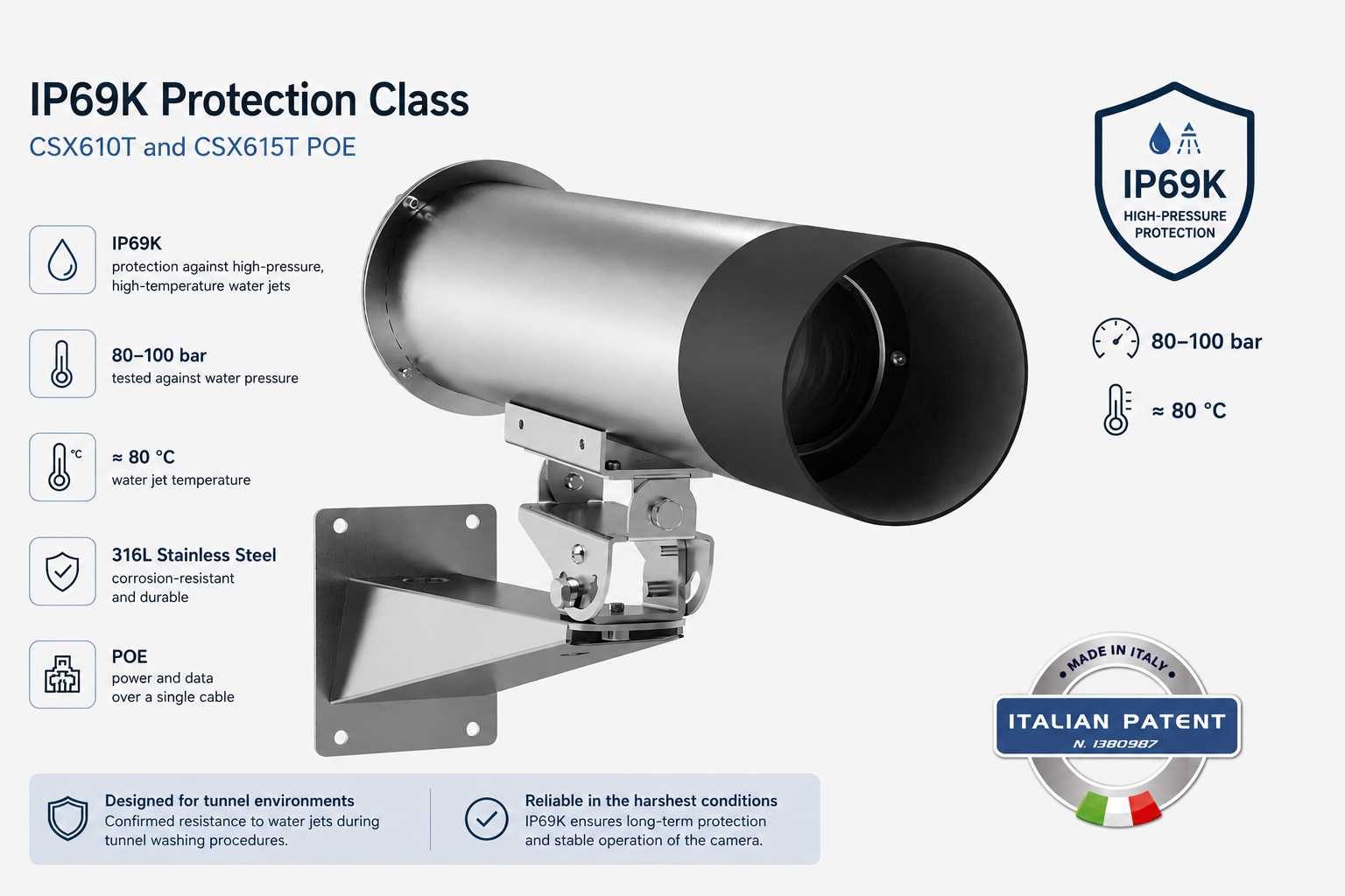
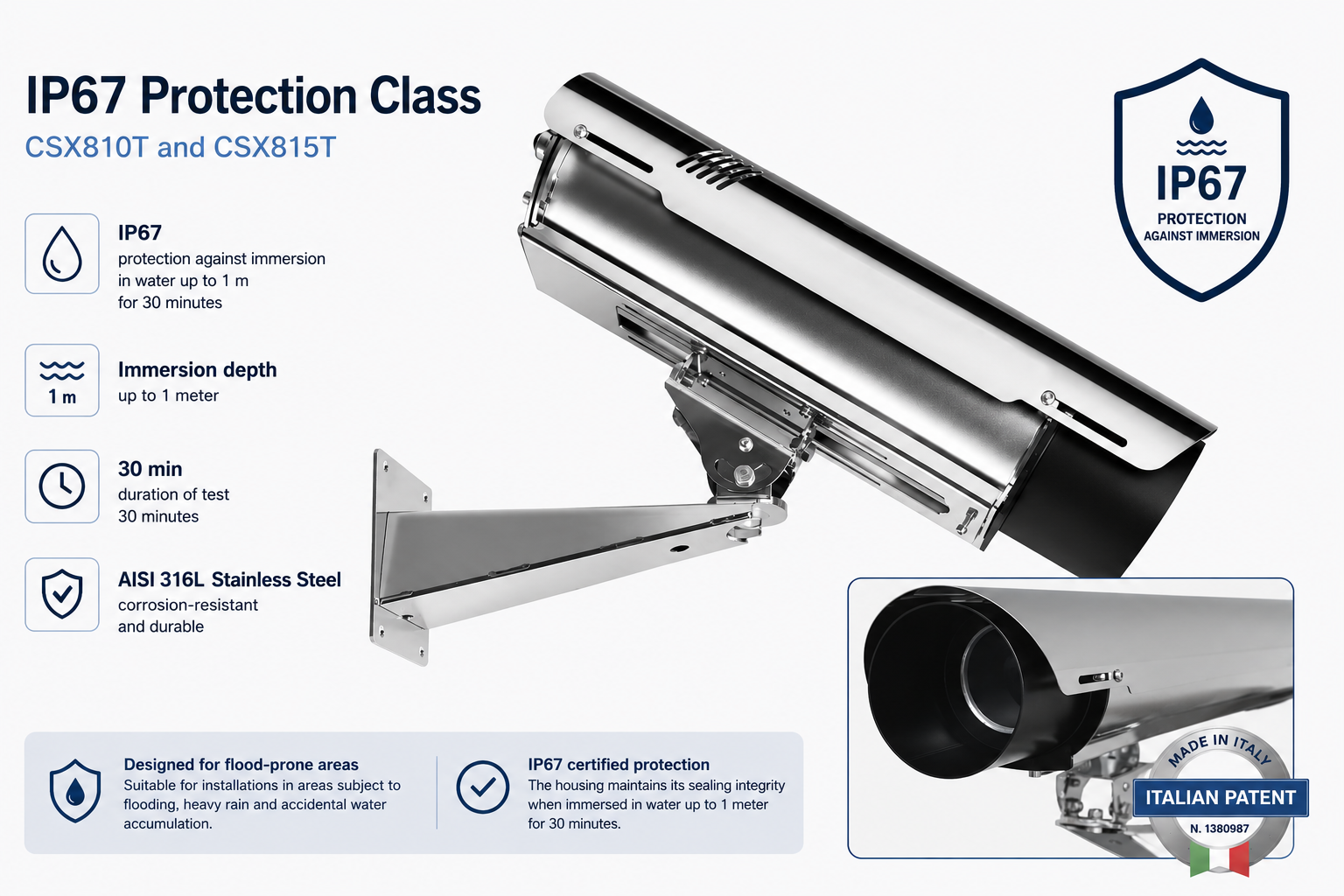
The practical implication is that the marking describes a specific exposure scenario. Selection should therefore follow the scenario actually present at the site. The smaller housing size is oriented toward regular high-pressure washing; the larger size is rated for temporary immersion.
At the same time, the absence of a particular rating does not prove that the housing would fail under that exposure. It means that the corresponding test is not stated in the specification. If both exposure scenarios are credible at the site, the configuration should be confirmed with the manufacturer before the project documentation is finalized.
Practical implication.
Where high-pressure washing is part of the site maintenance procedure, the choice within this series narrows to CSX610T or CSX615T POE, with flooding risk assessed separately for the specific mounting elevation. Where washing is manual or not required, the 8xx models become viable and provide additional internal space.
Housing Material: Why the Stainless-Steel Grade Belongs in the Specification
“Stainless-steel housing” is not a sufficiently precise requirement for a tunnel specification.
AISI 304 and 316L behave differently in chloride-rich environments. 316L contains approximately 2–3% molybdenum, which is absent from 304 and substantially improves resistance to pitting and crevice corrosion. In a tunnel exposed to road treatment chemicals, this difference directly affects housing service life.
All Global Proof models reviewed here are manufactured entirely from AISI 316L, including the wall-mount bracket. The fasteners are stainless steel, with A4 explicitly specified for the 8xx models.
Electropolishing, also listed for all models, is not simply a cosmetic treatment. A smoother surface reduces contaminant adhesion and reduces potential initiation sites for localized corrosion.
Thermal Management and Housing Controls
The specified operating range with heating is the same for all models reviewed: −20 to +60°C.
The lower limit can be extended with a dual heater, ordered as a separate accessory together with the housing. This is one detail that is easy to miss during ordering: RD600, RD615, and RD815 extend the lower operating limit to −30°C, while RD810 extends it to −45°C.
The housing controls operate at fixed thresholds:
- the heater switches on at +15°C and off at +22°C (±3°C);
- thermostatically controlled ventilation switches on at +37°C and off at +27°C (±3°C).
Between +22 and +37°C, both systems are inactive. Within this range, the camera’s thermal conditions are determined by its own heat dissipation and the heat exchange between the housing and the surrounding environment.
For a higher-power camera installed in a tunnel with elevated ambient temperatures, this needs to be checked separately: the housing controls do not intervene within this temperature band.
It is also useful to distinguish the roles of the individual components. Ventilation equalizes the temperature inside the housing and prevents heat generated by the camera from accumulating locally. That is what it is designed to do.
The reference condition for thermal assessment, however, remains the tunnel air temperature. In warmer tunnel sections, the camera’s thermal balance should be evaluated against that ambient condition.
PoE: Six Watts That Are Easy to Miss
In non-PoE versions, the heater is powered by a separate supply — 230 VAC, 24 VAC/VDC, or 12 VDC depending on the version — and consumes up to 30 W.
In the PoE versions, all equipment in the housing operates from a single cable. The camera, heater, and ventilation share the power budget of one PoE port. The heater is rated at 5 W and the ventilation at 1 W.
Both PoE models — CSX615T POE and CSX815T POE — are specified as compatible with IEEE 802.3af and 802.3at. The actual available power therefore depends on the switch port class.
| Port standard | Power available at the device | Heating | Ventilation | Remaining for camera |
|---|---|---|---|---|
| IEEE 802.3af | 12.95 W | 5 W | 1 W | ≈ 7 W |
| IEEE 802.3at | ≈ 25.5 W | 5 W | 1 W | ≈ 19.5 W |
Housing consumption figures are based on the manufacturer’s technical data; power available at the device is based on IEEE 802.3af/at parameters. The internal camera power-delivery arrangement should be confirmed with the manufacturer for the specific camera model.
The practical conclusion is simple: select the PoE class based on camera consumption + 6 W, not on camera consumption alone.
Approximately 7 W remaining under 802.3af is sufficient only for relatively low-power cameras. For a heated housing, 802.3at therefore becomes the practical choice for many camera configurations.
The second difference concerns cabling. CSX610T has two metal PG13.5 cable glands, while the PoE versions have a single M25 entry.
One entry means one cable. A configuration using PoE for the camera plus a separate heater supply is therefore not available in the standard PoE arrangement.
The third difference is dimensional and applies only to the larger housing size. The 8xx PoE version provides 260 mm of usable internal length, compared with 280 mm for the non-PoE version. There is no corresponding difference in the smaller size: both CSX610T and CSX615T POE provide 250 mm.
The project-level implication is that PoE reduces cabling infrastructure but transfers the power requirement to the network switch and its available PoE budget. With dozens of cameras, this stops being an installation detail and becomes a parameter in active network-equipment selection.
Mounting Geometry and Service Access
Two design features of the tunnel series directly affect installation and maintenance effort.
Three-axis mounting joint. The additional tilt axis allows the housing to be installed on a curved tunnel crown or on a wall that is not perpendicular to the mounting surface, while using the same mounting configuration for both wall and ceiling installations.
For the design engineer, this reduces the number of bracket variants that need to be specified — and, in turn, the number of components that can be confused during procurement or installation.
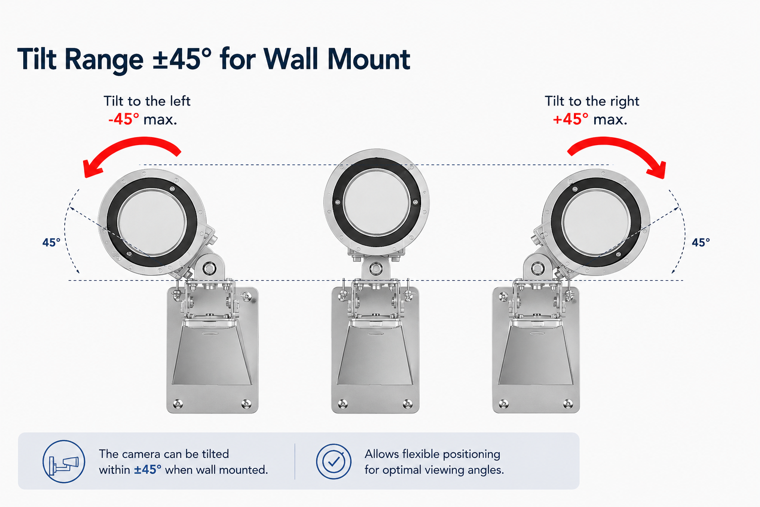
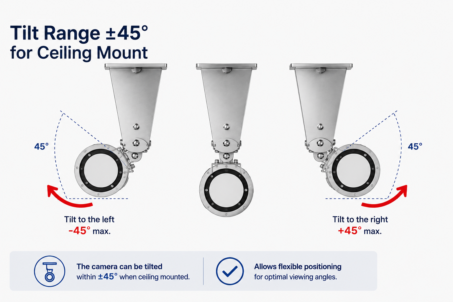
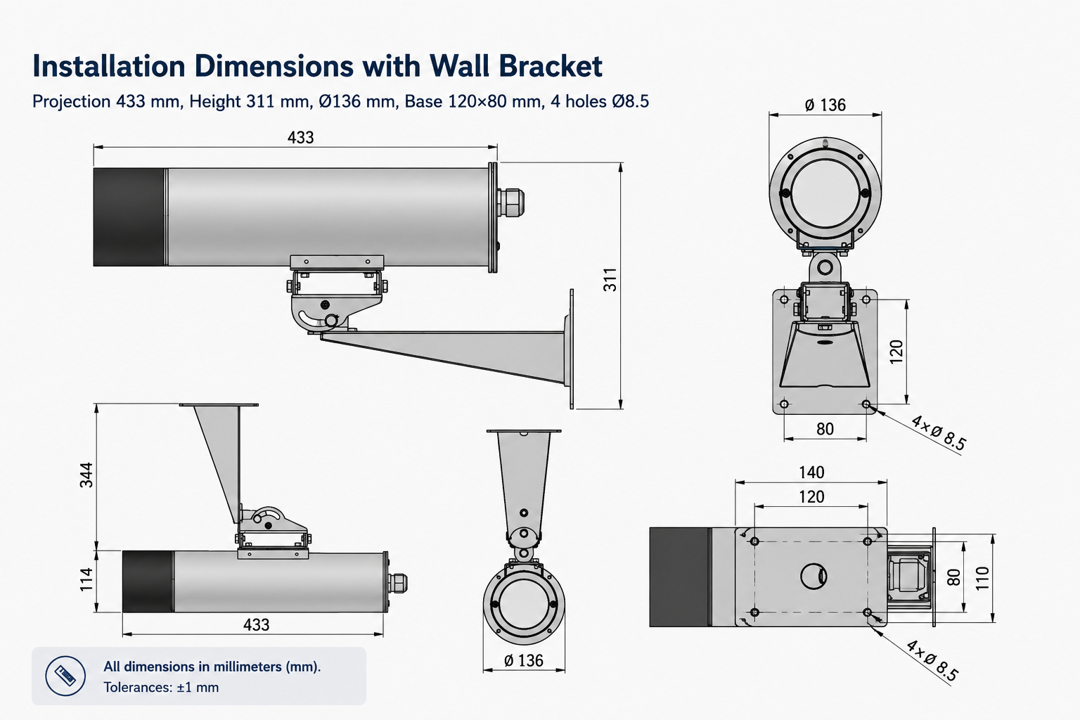
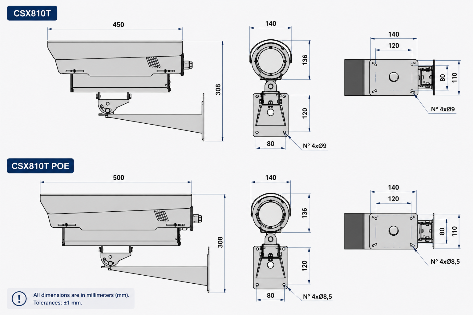
Slide-out design. The camera can be removed without dismantling the entire housing assembly, reducing the time technicians need to spend working at height.
Several points should be factored into maintenance planning.
Both features reduce the time spent working at height, but neither eliminates the need to access the housing physically. Service cost is therefore driven more by the number of site visits than by the duration of each intervention. That is the variable that should be reflected in lifecycle cost calculations.
The second consideration is seal integrity. If a housing will return to service in an environment where high-pressure washing is routine, maintenance should include an inspection of the seals rather than focusing on the camera alone. The appropriate inspection interval should be agreed with the manufacturer, as it depends on the washing regime at the specific site.
A safety cable and retaining screws are included with the CSX610T. For installations above the roadway, the safety-retention requirement should be stated explicitly in the specification and the implementation confirmed during product selection. Anti-theft retention and fall protection serve different purposes and should not be treated as interchangeable.
Two additional details should also be considered in the specification.
The 8xx models are supplied with an AISI 316L sunshield. This is relevant at tunnel portals and exposed locations; for installations deeper inside the tunnel, it is primarily a configuration consideration rather than a functional requirement.
Conversely, the relatively low weight of the housings allows them to be installed on compact pan-and-tilt units using the SNF800 adapter plate. The allowable camera weight for this configuration should be confirmed during product selection.
Camera Dimensions and Optics
The second primary selection parameter is the overall size of the camera-and-lens assembly. It needs to be evaluated alongside the site’s washing regime, not as a separate, sequential check.
| Parameter | CSX610T | CSX615T POE | CSX810T | CSX815T POE |
|---|---|---|---|---|
| Protection rating | IP69K | IP69K | IP67 | IP67 |
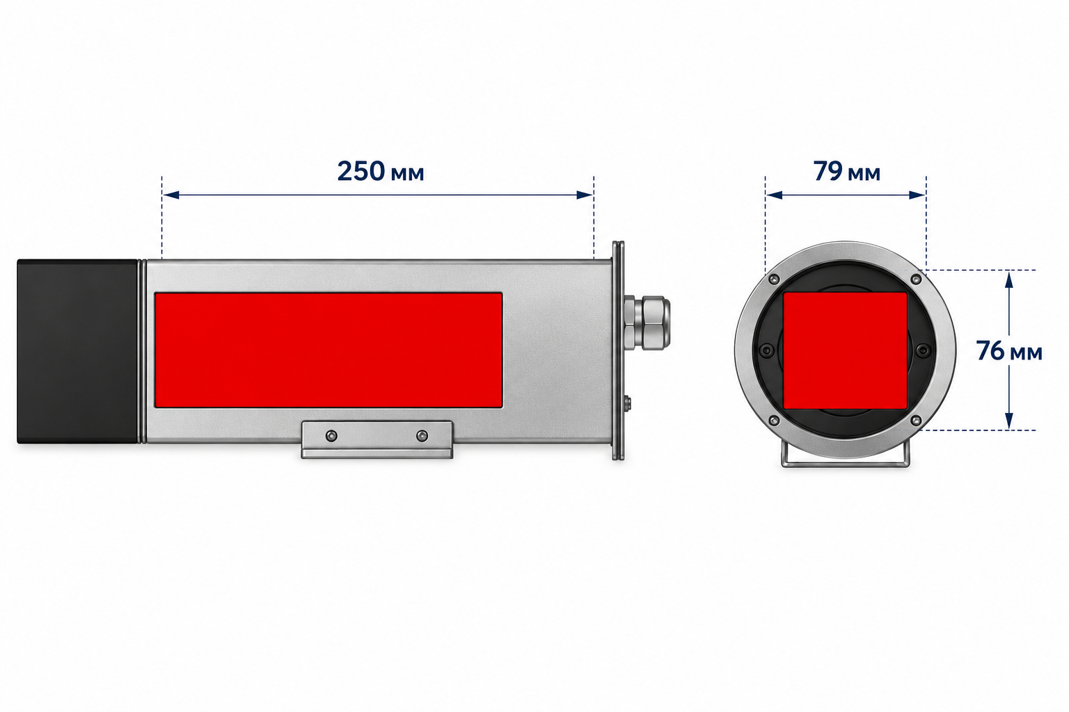
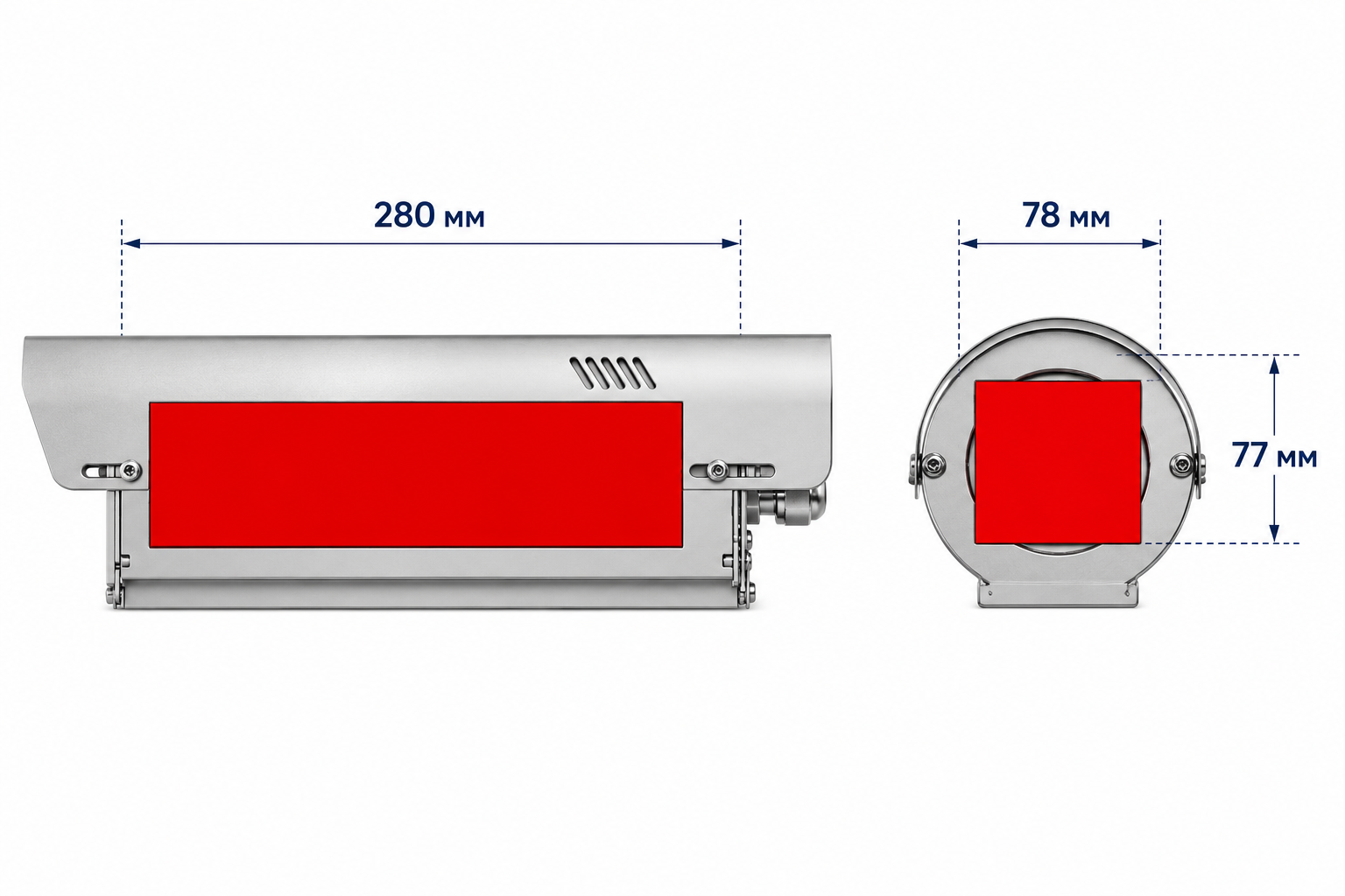
| Usable internal space | 79 × 76 mm | 79 × 76 mm | 78 × 77 mm or Ø95 mm | 78 × 77 mm or Ø95 mm |
| Usable internal length | 250 mm | 250 mm | 280 mm | 260 mm |
| Optical window | Ø75 mm | Ø75 mm | Ø75 mm | Ø75 mm |
| Power supply | 230 VAC / 24 VAC/VDC / 12 VDC | PoE 802.3af/at | 230–110 / 24 / 12 VAC | PoE 802.3af/at |
| Heater power | 30 W | 5 W | 30 W | 5 W |
| Dual-heater option | RD600, down to −30°C | RD615, down to −30°C | RD810, down to −45°C | RD815, down to −30°C |
| Cable glands | 2 × PG13.5 | 1 × M25 | Not specified | 1 × M25 |
| Sunshield | Not specified | Not specified | Yes | Yes |
| Optical cleanliness approach | Clean glass | Clean glass | Clean glass | Clean glass |
| Weight, kit with bracket | 6 kg | 6 kg | 5 kg | 7 kg |
The table makes the product-line logic clear. The smaller housing size is designed for installations where regular high-pressure washing is part of the operating environment. The larger size provides additional internal space for camera-and-lens assemblies that exceed the smaller housing’s capacity.
Camera dimensions and washing regime therefore need to be evaluated together: in combination, they determine the appropriate housing size.
One additional practical point is worth noting. Product listings in distributor or online catalogs can sometimes mix specification fields across related product series. Parameters used for project specifications should therefore be taken from the manufacturer’s technical documentation.
A second observation concerns the optics. All four models use the same Ø75 mm optical window.
The larger internal volume of the 8xx series therefore accommodates a larger camera body, but does not provide a larger optical aperture.
This leads to a practical consideration when selecting the optics: a Ø95 mm camera mounting envelope does not, by itself, determine which lens will operate through a Ø75 mm optical window without vignetting. As a practical guideline, the usable lens diameter is roughly limited to 70–75 mm.
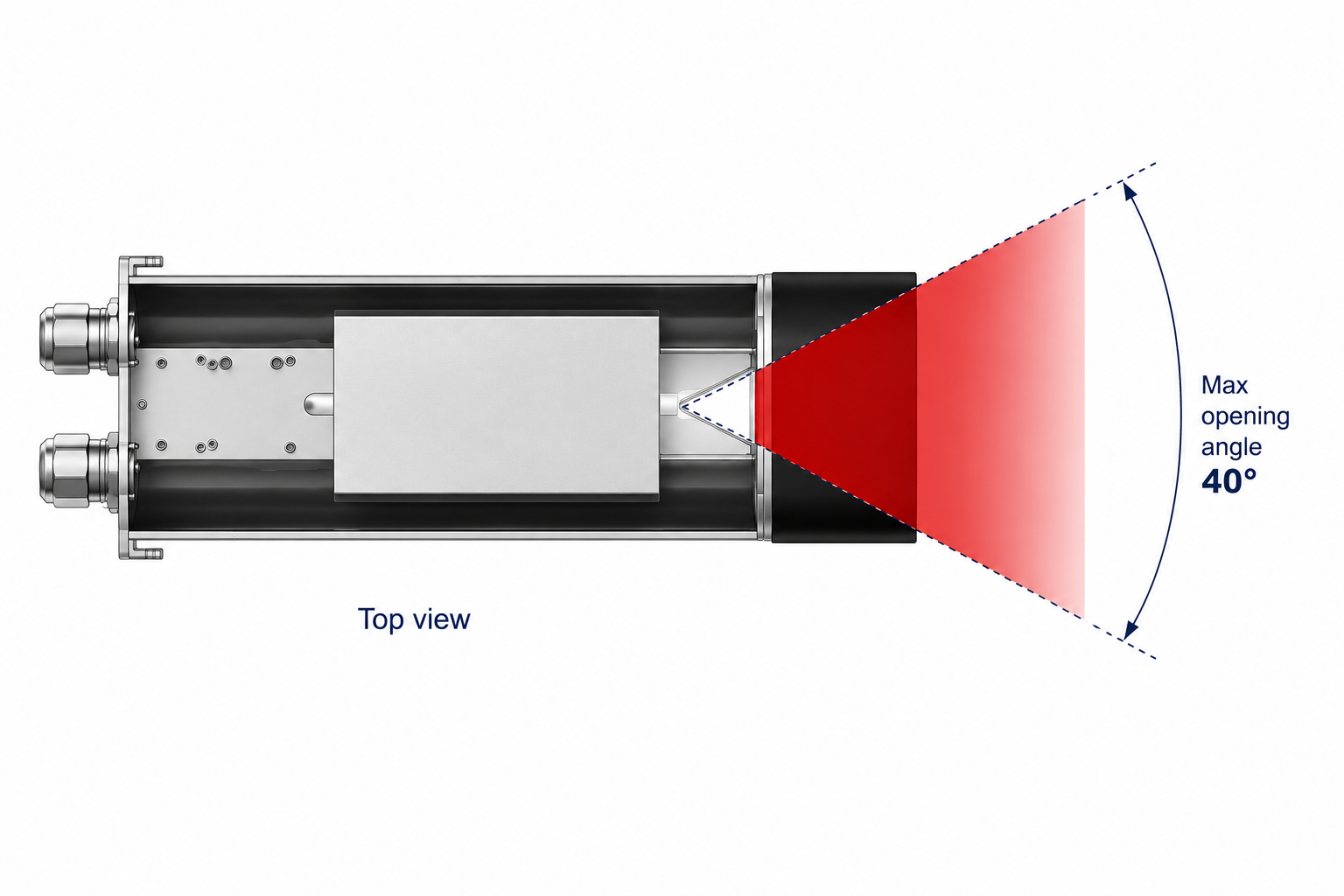
The manufacturer also specifies the maximum field of view available through the housing window. The specific camera-and-lens / housing combination should therefore be verified during product selection.
Selection Sequence
The order of these decisions matters. A common source of design rework is selecting the camera before the housing and establishing the site’s washing regime only after installation.
Obtain the site’s washing specification — pressure, temperature, frequency, and nozzle distance. This determines whether the 8xx series is a viable option in the first place.
Account for drainage conditions at the specific mounting elevation. IP69K covers high-pressure water-jet exposure, but not immersion.
Check the camera-and-lens dimensions against the available internal space: 79 × 76 × 250 mm for the 6xx series, and 78 × 77 mm or Ø95 mm × 280 mm for the 8xx series (260 mm for the CSX815T POE).
Cross-check Steps 1 and 3. If the site requires IP69K but the camera does not fit the smaller housing, the constraint cannot be resolved simply by moving to the larger model. The alternatives are a different camera, a different housing, or — where operationally acceptable — an adjustment to the washing procedure. This should be resolved during product selection.
Establish the site temperature profile and determine whether a dual heater is required, taking into account the −30°C and −45°C lower-temperature limits of the respective configurations.
Evaluate the power infrastructure. For PoE configurations, select the port class based on camera load + 6 W.
Review the installation geometry — mounting joint, adapters, and whether a pan-and-tilt unit is required.
Compile the questions that require manufacturer confirmation for the specific project.
| Site condition | Applicable models | Additional considerations |
|---|---|---|
| Regular high-pressure washing | CSX610T, CSX615T POE | Camera-and-lens assembly must fit within 79 × 76 × 250 mm; for mounting positions at low points in the longitudinal profile, consider site drainage conditions |
| Manual washing or no pressure washing; larger camera | CSX810T, CSX815T POE | Verify that IP67 matches the actual maintenance regime; confirm the cable-entry configuration |
| Limited power infrastructure | CSX615T POE, CSX815T POE | Select the PoE port class based on camera load + 6 W; a single cable entry serves both the camera and housing systems |
| Ambient temperature below −30°C | CSX810T with RD810 dual heater | Verify that IP67 is compatible with the site’s washing regime |
Standards and Regulatory Context
Directive 2004/54/EC establishes minimum safety requirements for road tunnels longer than 500 m on the TEN-T network, including requirements related to monitoring systems. PIARC guidance recommends camera spacing of approximately 50–80 m for automatic incident detection where overlapping coverage is required. In Ukraine, tunnel infrastructure design is governed by DBN V.2.3-27:2023.
These documents influence the required number of cameras — and therefore the number of housings in the project — but do not define the technical specification of the housing itself. In practice, housing specifications are based on the applicable international standards.
What to Confirm During Product Selection
Several parameters are best resolved before the specification is finalized, rather than left to be addressed during installation or operation.
| What to confirm | Why it matters |
|---|---|
| Mechanical impact resistance | For locations where contact with maintenance equipment or oversized vehicles is possible |
| Site contamination profile | Dry dust and oily deposits lead to different expected intervals between optical maintenance |
| Optical window material and thickness | To assess resistance to mechanical impact |
| Recommended seal inspection interval | To incorporate it into the maintenance schedule alongside tunnel washing |
| PoE power-delivery arrangement to the camera | To calculate the available power budget for the specific camera model |
| Compatibility with site cleaning agents | Where the operator uses specialized cleaning chemicals |
| Availability of CAD or BIM models | For integration into project design documentation |
These are standard pre-design questions — exactly the type of issues we resolve together with the design engineer while the configuration is still being selected.
What This Means in Practice
Housing selection for a camera installed in a tunnel is driven primarily by two project-specific parameters, neither of which comes from the product catalog: the site’s actual washing regime and the overall dimensions of the camera-and-lens assembly.
The remaining factors — material, heating, power architecture, and mounting geometry — refine the configuration, but do not fundamentally change the selection logic.
In the product line reviewed here, these two requirements map to different housing sizes. The smaller housing is certified for high-pressure washing and provides 79 × 76 mm of usable internal space with a usable length of 250 mm. The larger housing provides additional internal capacity for camera-and-lens assemblies that do not fit within those dimensions.
The two requirements therefore need to be evaluated together — and resolved before the specification is finalized, not after installation.
The practical recommendation comes down to two questions that should be answered before a specific housing model enters the specification:
How is the tunnel cleaned, and under what conditions?
What camera-and-lens combination is planned for the project?
Those two answers narrow the field faster and more reliably than comparing product specifications alone.
Next Step
FortiSec works with Global Proof as a project-focused distributor, supporting configuration selection while the specification is still open to refinement.
If you are preparing project documentation or a specification: send us the camera-and-lens model together with the site’s washing procedure. We will check dimensional compatibility with the housing and verify that the specified protection rating matches the actual maintenance conditions — before the configuration is committed to the project specification.
If you need information that is not covered in the standard technical documentation — seal behavior and recommended inspection intervals, Clean glass performance under specific site conditions, mechanical resistance in areas exposed to maintenance equipment, or dimensional data for project documentation — we can provide guidance based on practical experience with the installation and operation of these housings.
If you are evaluating the solution for deployment across multiple locations: we can work through the configuration for a representative site — housing size, heating, PoE class, and mounting hardware — and calculate the total power budget for the entire tunnel section.
Technical data are based on Global Proof documentation: CSX610T (rev. 2506), CSX615T POE (rev. 2506), CSX810T (rev. 2814), CSX815T POE (rev. 2510), and CSX828P (rev. 0615). Test methods are referenced to ISO 20653 / DIN 40050-9 and IEC 60529. Power parameters are based on IEEE 802.3af/at.