Engineering overview
STI in Ukraine:
Activation and Physical Protection Components That Shape System Performance
This article looks at the parameters that matter when selecting this class of equipment, where its practical limits lie, and why configuring some STI product lines requires engineering work in its own right.
Components That Shape System Performance in Real-World Operation
In complex security projects, one category is almost always specified last: push buttons, manual call points, protective covers, guards, and mounting accessories. Core subsystems — video surveillance, perimeter protection, and access control — go through technical evaluation, pilot testing, and architecture review. A push button, by contrast, is often treated as an afterthought and selected largely on price because, after all, “it just closes a contact.”
That logic starts to break down in operation. A false activation of a manual call point in a hospital corridor can trigger an evacuation in a critical care area. Corroded contacts in an emergency door release button can mean a service call. A damaged detector in a warehouse aisle can mean an unplanned repair — and an issue at acceptance. The cost shows up somewhere other than where the original decision was made.
FortiSec’s relationship with STI started with a project requirement, not a distribution strategy. Large perimeter security projects called for outdoor-rated manual alarm activation devices, but the available options did not match the engineering standard of the rest of the system.
In practice, fire alarm manual call points were sometimes used in place of dedicated alarm buttons. They were available in outdoor-rated versions, but using a device marked with a burning-building symbol as an alarm button on a high-value perimeter was a workaround, not a solution. Interestingly, FortiSec’s first actual order in this category was not for buttons at all. It was for more than a hundred protective guards for a mix of equipment, including exit signs, loudspeakers, and notification devices.
STI: Experience, Manufacturing, and Industry Standing
Safety Technology International has operated in this category for more than 45 years and continues to manufacture in both the United States and the United Kingdom. EU deliveries are supported by a logistics hub in Ireland — a practical consideration when planning lead times for European projects.
STI’s industry standing is also reflected in its professional affiliations: the company has been a member of the Security Industry Association (SIA) in the United States since 1987, participates in the British Security Industry Association’s Export Council, and joined Euralarm’s Fire Section in 2024. The latter places STI within the European industry conversation around fire safety standards and regulation, rather than limiting its industry presence to the US market.
An indirect but telling signal is the way the Stopper trade name has entered industry vocabulary as a near-generic term for protective covers for manual call points. Importantly, this usage appears in independent industry sources, not just in the manufacturer’s own materials.
The Engineering Principle Behind the Entire Portfolio
STI’s portfolio is not simply a collection of unrelated accessories. Across its product lines, the same design principle appears again and again — one that can be traced back to a 1980 patent: a controlled-access barrier that protects the device without preventing its intended operation.
The patent is quite specific about how this principle works in practice.
The cover keeps the protected device fully visible.
Opening it triggers an alarm.
Just as importantly, the design prevents the cover from being quietly returned to its closed position: the alarm continues to sound until someone manually realigns and closes the cover.
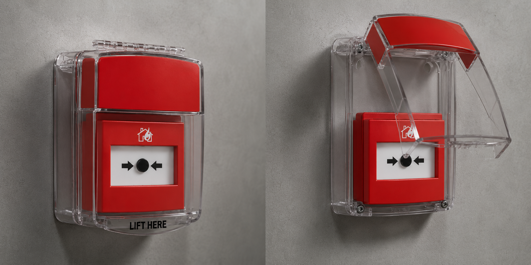
In a fire emergency, access to a manual call point must remain immediate; in an industrial environment, an emergency stop button must still operate on the first press. The engineering objective, then, is to add one deliberate action — not to make the device harder to access.
Over time, the same principle moved from passive protective covers into STI’s own activation devices: a recessed button mechanism, a contoured profile designed to require a deliberate press at the center, and key-only reset after activation. Here, protection is built into the device itself rather than added as a separate layer.
Portfolio by Engineering Function
A more practical way to navigate the portfolio is not by catalog category, but by two questions: what are we protecting or activating, and what condition are we designing for?
| Engineering objective | Primary risk | STI product class | Product families |
|---|---|---|---|
| Reduce false activations of manual call points | Accidental or malicious activation | Call point covers | Euro Stopper, Stopper II, Call Point Stopper, Enviro Stopper |
| Protect a button or call point from impact, dust, and weather | Mechanical damage and environmental exposure | Universal protective covers | Universal Stopper, Low Profile Universal Stopper |
| Protect smoke or heat detectors | Vandalism and mechanical impact | Detector covers and guards | Polycarbonate and steel Damage Stopper models, Steel Web |
| Protect notification devices, cameras, PIR detectors, and lighting | Vandalism and physical damage to exposed equipment | Protective guards | More than 50 form factors designed for specific devices |
| Protect equipment from environmental exposure | Moisture, dust, and low temperatures | Protective enclosures and cabinets | EnviroArmour, metal and polycarbonate cabinets |
| Provide a manual activation point | Need for a dedicated activation device | Activation devices | Stopper Stations, G3/GF/GFC, ReSet, StopperSwitches, NoTouch |
| Monitor emergency exits and life-safety equipment | Unauthorized use or theft | Standalone monitoring devices | Exit Stopper, Theft Stopper, fire extinguisher alarms |
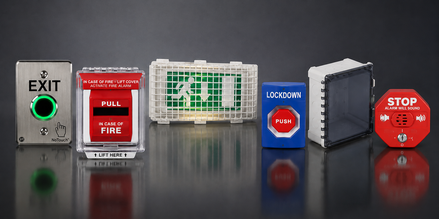
Activation Devices: Where “Just a Button” Stops Being Just a Button
The main value of this product group lies not in any single feature, but in the range of activation, reset, switching, and labeling configurations supported within the same core design.
A Button with a Camera — Not a Camera with a Button
Perhaps the least obvious product in the portfolio is a push button with an integrated IP camera. Why such a device exists becomes clearer when viewed in the context of perimeter security projects.
Along a secured perimeter, alarm buttons are typically installed at regular intervals, often tens of meters apart. Perimeter cameras, meanwhile, are positioned to monitor the perimeter line itself — not the area immediately in front of each button. As a result, when a button is activated, the system receives the event but not necessarily the visual context: who pressed it, under what circumstances, and what was happening nearby. Integration through a camera’s dry contacts or through an integrated security platform can provide a timestamp and associated video — but that video may come from a camera looking in a different direction.
The camera integrated into the button addresses precisely this gap. According to the manufacturer, it provides 5 MP resolution at 30 fps, a 180° diagonal field of view, 12 V DC or IEEE 802.3af PoE power, H.264/H.265/H.265+ compression with separate processing for dynamic and static scenes, and ONVIF support. For the system designer, the practical implication is more important than the specification list: the device can be integrated into an existing VMS as a standard IP video source, without introducing a separate video subsystem.
The product lines are differentiated primarily by application, not simply by whether a camera is included. GF is a fire alarm activation device without a camera, GFC is the camera-equipped fire alarm version, and G3 is designed for multi-purpose applications. The choice between them depends on the application and the relevant certification requirements.
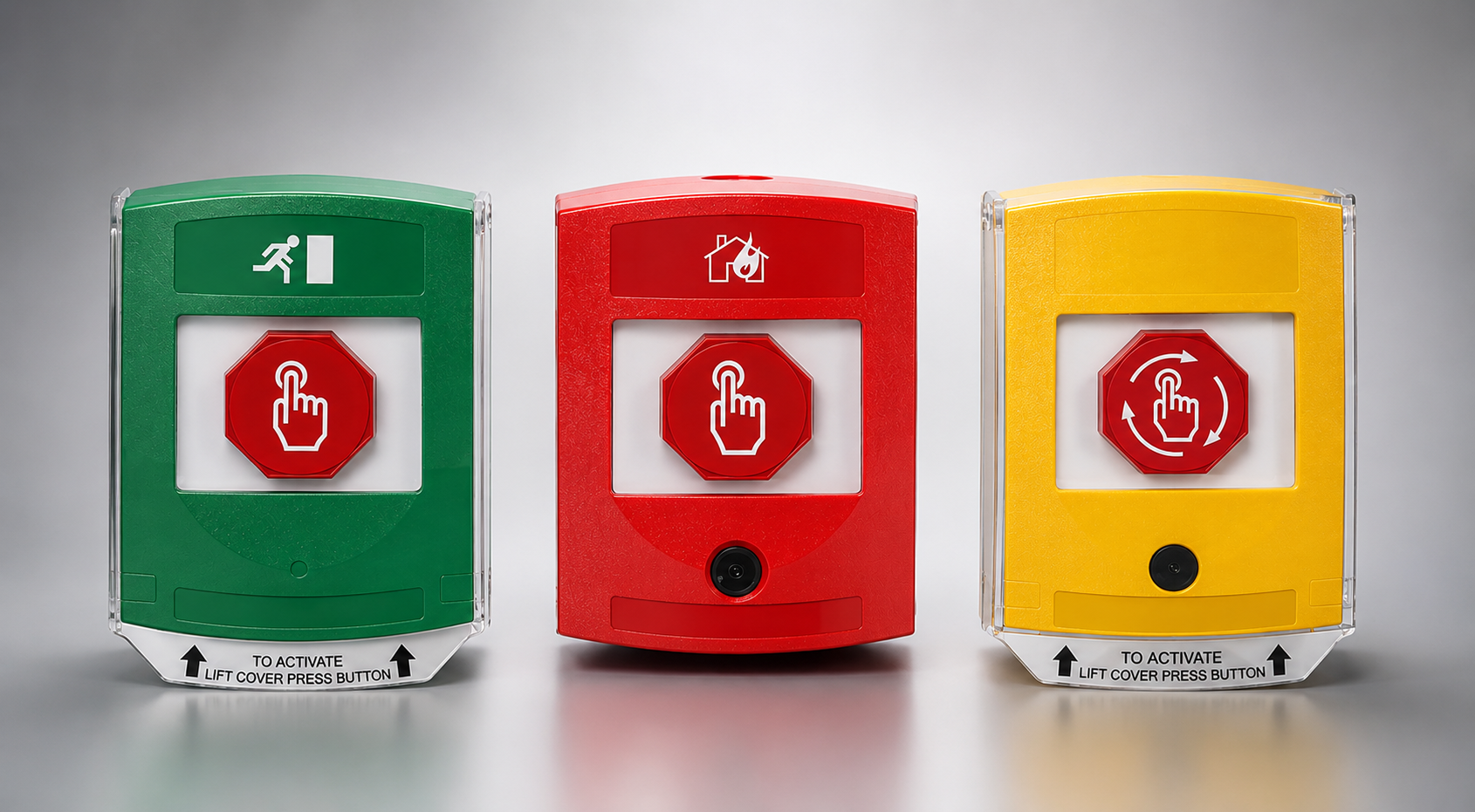
One constraint should be clear from the outset: these devices are intended for indoor installation. For outdoor applications, the device must either be installed in a suitable STI polycarbonate protective enclosure or replaced with a product line specifically designed for outdoor use. Switching options include a double-pole relay output with two Form C contacts (NO/NC), as well as single-pole configurations. Exact contact ratings should always be verified against the datasheet for the specific model being specified.
Stopper Stations: Configurability as an Engineering Tool
The Stopper Station platform is built around the idea that a single core design should support different application requirements without requiring a different device architecture. Ten activation and reset configurations are available, including push, standard fire-service key, or cylinder-key operation; momentary, latching, and turn-to-reset mechanisms; as well as a pneumatic timed-reset option that requires no electrical power.
More significant from a system design perspective is that each station can accommodate up to three contact blocks. One is fitted as standard, with provision for two additional blocks. Each block provides two independent Form C contacts rated at 10 A at 125/250 V AC. This allows a single device to serve up to three separate functions or interface with three independent system circuits.
This has a direct impact on both the device specification and the cabling architecture. Typical applications for the series include emergency lockdown with shutter deployment, emergency-exit monitoring, production shutdown, manual alarm activation, shutdown of pumps and stairwell pressurization systems, and police assistance calls. The platform is also available in outdoor-rated and illuminated configurations, with an activation delay timer and a replaceable protective shield available as separate options.
ReSet: A Resettable Alternative to Break Glass
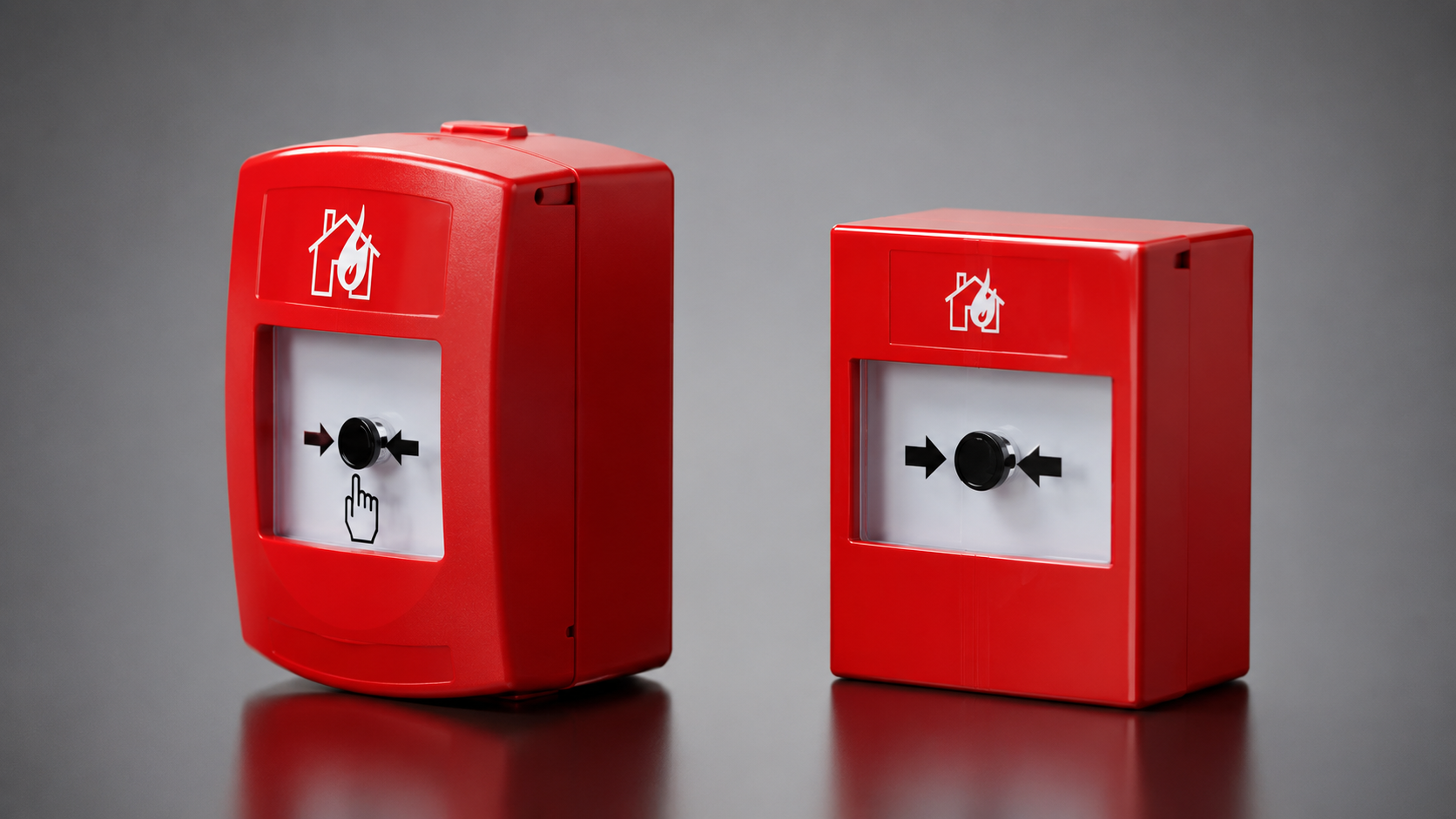
ReSet manual call points use a mechanism designed to replicate the tactile feedback of breaking glass. When activated, the element provides a distinct tactile response and a visible activation indicator drops into view — but the element itself remains reusable. Reset is key-operated only, with reset keys supplied with the device.
The operational impact is straightforward: there is no need to stock replacement break-glass elements or dispatch a service technician to replace one after every activation, including during drills and routine testing. The series is available in indoor versions as well as IP67-rated models for outdoor installation. Installation is also simplified by removable terminal blocks: the field wiring can be terminated separately, after which the terminal block is plugged into the device.
The harmonized standard DSTU EN 54-11:2004 specifies an activation force of 25–80 N for manual call points, while a frangible element must withstand a force of 22.5 N for five seconds without breaking. The over-center spring mechanism follows the same principle: it provides resistance up to a defined threshold, followed by a clear transition into the activated state.
Key Control and Device Labeling
Two parameters are often addressed late in the procurement process, even though both can affect delivery lead times and the site’s security procedures.
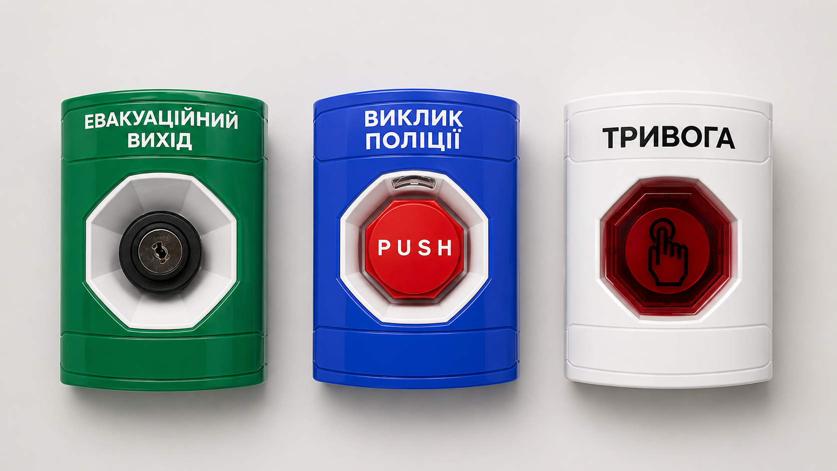
Keys. In one project involving approximately 800 stations, around 200 were key-operated emergency-entry devices. The manufacturer confirmed that both keying strategies were available: individually keyed doors or a common key across the entire project. The appropriate configuration is determined by the site’s key-management protocol, not by the equipment supplier.
Labeling. Devices can be supplied with English or Ukrainian text, or with pictograms. Pictograms remove the need to rely on language altogether and can be particularly effective at sites with international personnel or in situations where the required action must be understood within seconds. Ukrainian-language labeling is applied by FortiSec, and units with localized markings have already been produced, so localization does not add manufacturing lead time at the STI factory.
Protective Enclosures and Guards: Parameters with Design Implications
A common feature across STI’s polycarbonate enclosures is UV-stabilized material and a device-agnostic design: they can accommodate not only STI activation devices, but also third-party equipment with compatible dimensions.
Two Mounting Methods
The terminology is worth defining explicitly here, because this is where specification errors tend to occur.
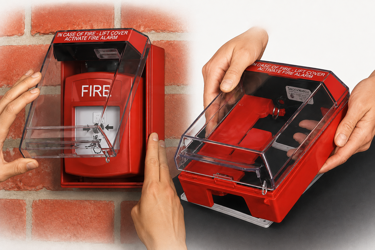
The first mounting method uses an open-back cover installed over an existing wall-mounted device and secured at four mounting points. The protected device does not need to be removed, and the existing field wiring remains untouched. For devices that project from the wall surface, 32, 37, or 50 mm spacers are available.
The second mounting method places the device inside the protective enclosure, with a rear backbox providing the mounting and wiring space.
The first mounting method is particularly relevant in retrofit projects: it allows the level of physical protection to be increased without replacing the existing equipment or modifying the field wiring, provided the device dimensions are compatible with the selected cover.
Levels of Physical Protection
| Series | Key distinction | Protection / environmental rating |
|---|---|---|
| Call Point Stopper | Compact design; front and side protection; spring-loaded front cover | Indoor use |
| Euro Stopper | Provision for tamper seals; optional 96 dB sounder; Glow Guide insert | Indoor use |
| Low Profile Universal Stopper | Low-profile design; sounder; LED indicator | IP54 |
| Universal Stopper | Domed cover; sounder; relay; more than 500 configuration options | IP54 |
| Stopper II | Larger cover; 95 or 105 dB sounder; heated version available | IP54 in weather-resistant configuration |
| Enviro Stopper | Highest environmental protection rating in the protective-cover range | IP56 / IP66 |
| EnviroArmour | Enclosure for control panels and sensitive electronics | IP54; IK09 for reinforced versions |
Understanding these protection ratings is important for correct product selection. IP54 provides limited protection against dust ingress and protection against splashing water; IP56 and IP66 provide protection against more powerful water jets, provided the enclosure is installed correctly and the seals remain intact. IP67 adds protection against temporary immersion — it does not mean that the enclosure is designed for continuous submersion.
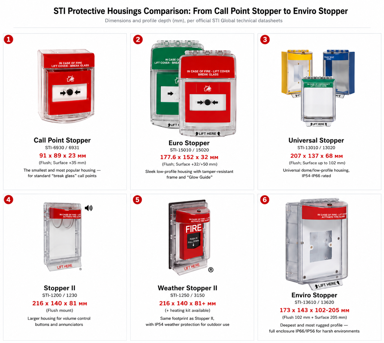
One distinctive Euro Stopper option is Glow Guide, a photoluminescent insert around the perimeter of the frame that makes the enclosure visible in the dark without requiring any electrical power. On evacuation routes, that passive visibility can be a meaningful selection criterion in its own right.
Models equipped with a sounder can be powered either by an internal battery — 3 V lithium or 9 V PP3, depending on the series — or from an external 12–24 V DC supply. An optional relay output is also available on selected configurations.
Protective Guards: Why “Bigger for Safety” Does Not Work
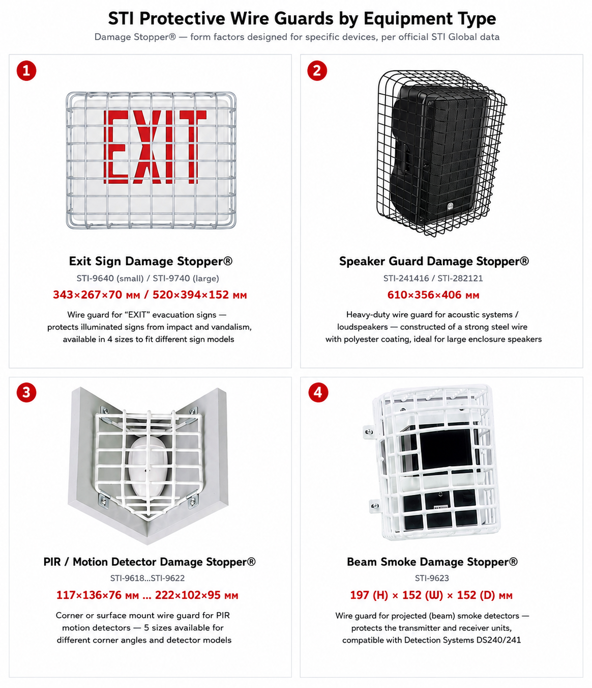
The range includes more than 50 standard form factors for equipment such as exit signs, floodlights, point and beam smoke detectors, strobes, loudspeakers, motion detectors, bells, clocks, and fluorescent luminaires. Guards are available in steel with polyethylene or polyester coating, as well as in stainless steel. Selected series also feature adjustable mounting tabs, allowing installers to position the fixing points where they best suit the installation.
The main practical challenge is dimensional compatibility. The device being protected is rarely a simple rectangular shape: dimensions may vary across the housing, with tapers, projections, and other geometric features. Selecting a guard based only on maximum overall dimensions can fail in either direction — the guard may not fit at all, or it may be unnecessarily large for the device. For this reason, fit should ideally be verified with a physical sample before the guard is added to the project specification. Samples for compatibility checks can be requested from FortiSec.
Standalone Contact-Based Alarm Systems
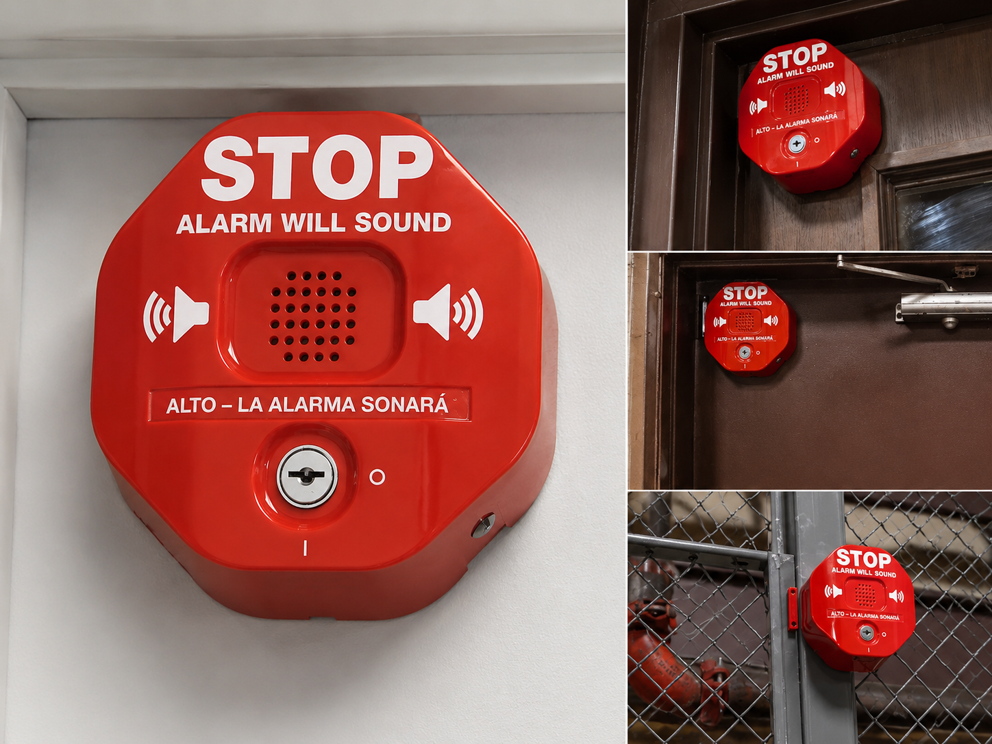
This is a separate group of self-contained devices that combine one or two magnetic reed contacts, a local sounder with strobe, and key-operated arming in a single enclosure. Depending on the model, power is supplied either by an internal battery or from an external 12–24 V DC source.
Exit Stopper monitors emergency exit doors, providing a loud audible and visual warning when a door is opened without authorization. Rescue-equipment alarms use a different mechanism. A fire extinguisher is secured with a retaining strap; when the extinguisher is removed, the strap pulls free from the alarm housing and activates the sounder. The system does not obstruct access to the extinguisher in an emergency, but any attempt to remove or relocate it becomes immediately noticeable. The same principle can be applied to AEDs, first-aid kits, and evacuation chairs. Direct equivalents in this product category are not widely represented on the Ukrainian market.
Application Constraints to Consider During Project Design
Certification across this portfolio is model-specific, not brand-wide. Compliance status therefore needs to be verified at the individual part-number level. Specifying the exact certified model gives the project documentation the required level of precision and reduces the risk of compliance issues during tender review and technical acceptance.
| Product | Verified certification / compliance status |
|---|---|
| ReSet Call Point, Series 01 (indoor version) and IP67 version | EN 54-11, Certificate No. 653a/01 — the only product line in this portfolio with EN 54-11 certification |
| Global ReSet (GR/GLR) | UL/cUL, ADA; the manufacturer’s official product information explicitly states “Not EN54-11 approved” |
| Stopper II (STI-1100/1130/1200/1230) | UL/cUL Listed, S2466; flush-mount version is ADA compliant |
| Stopper II — STI-1100/1130 only | Additionally FM Approved, OG6A2.AY; this approval does not extend to the rest of the series |
| Stopper Stations, G3, Station Shield | UL/cUL, S7255 |
| Smoke and heat detector guards | UL Listed, S3504 — applicable to the specified detector models |
| Notification appliance enclosures | UL, S7025 |
| NoTouch (stainless steel / aluminum) | CE, UKCA, IP65 |
Certification
A key structural point is that most STI retrofit covers are mechanical accessories installed over an already certified device, often from another manufacturer. The cover does not replace the underlying device or its certification; compliance of the protected device remains tied to that device and its manufacturer. Where certification requirements apply, the specific cover-and-device combination should be checked against the relevant approval and project requirements.
Several other parameters are project-specific rather than defined at the product-series level, so they should be established early in the design process:
- Impact resistance. A formal IK09 rating to IEC 62262 is confirmed for the reinforced fiberglass enclosure. For polycarbonate covers, the manufacturer describes impact resistance qualitatively rather than by a specific IK rating. Where a project specification requires a defined IK class, the rating should therefore be confirmed with the manufacturer for the specific part number before it is included in the project.
- Approvals. The portfolio includes confirmed UL/cUL certifications, FM Approvals for selected models, and EN 54-11 certification for ReSet Series 01. Where a project requires LPCB, VdS, or a specific RoHS declaration, the status should be verified with the manufacturer for the exact part number.
- Smoke and heat detector guards. A protective cover affects airflow around the detector, so compatibility needs to be considered as a specific cover-and-detector combination. UL Listing S3504 applies to the detector models identified in the relevant documentation; compatibility with other detectors should be confirmed separately. This is a straightforward check during product selection.
- Notification appliance enclosures. These enclosures incorporate perforations and clear sections specifically to minimize their effect on the sound and light output of the protected device. Actual performance should be verified by measurement after installation as part of the standard acceptance process.
- Camera guards. These guards provide protection against mechanical threats such as impact, thrown objects, or attempts to dislodge the camera. If the threat model also includes obscuring or painting over the lens, that risk needs to be addressed through the selection of a camera with the appropriate vandal-resistant design rather than through the guard alone.
- Indoor and outdoor use. G3/GF/GFC stations and key switches are designed for indoor installation. Outdoor applications require either an appropriate STI protective enclosure or a product series with its own outdoor-rated construction, such as IP67 stations or Waterproof ReSet models.
- Maintenance of sounder-equipped models. Battery replacement and sounder testing are required annually, while seals on weather-resistant models are typically replaced approximately every five years. Including these tasks in the maintenance schedule from the outset makes total cost of ownership more predictable. Where this maintenance cycle is difficult to support reliably, passive models without a sounder remain a practical alternative.
Ukrainian Regulatory Context: Reference Points for Project Design
DBN V.2.5-56:2014 (including Amendment No. 2, effective March 1, 2026), Clauses 7.2.14 and 7.2.15, requires protective measures for detectors installed below 2.2 m, provided that the protection does not interfere with the operation of the device. This reflects the same general engineering principle that underlies STI’s approach: physical protection should not compromise the intended function of the protected equipment. Unlike a number of international standards, however, the Ukrainian regulatory framework does not contain a direct requirement for protective covers over manual call points. Any compliance rationale for their use is therefore indirect and needs to be based on the applicable project requirements and operating conditions. Presenting such covers as a formal regulatory requirement in Ukraine would be inaccurate.
Law No. 4609-IX of September 18, 2025 requires educational institutions to install panic buttons, while the accompanying guidance specifically recommends placing the button in a discreet location inaccessible to children. In practical terms, this makes prevention of accidental or unauthorized activation an explicit design consideration. At the same time, according to the Ministry of Internal Affairs, 98.5% of schools already had such systems in place as of October 2025. This shifts much of the practical demand from first-time deployment toward upgrading existing installations and protecting installed devices against false activation.
Where These Solutions Make Engineering Sense
| Application | Risk and consequence | STI solution | Application requirement |
|---|---|---|---|
| Industrial perimeter | Activation without visual context; insufficient information to reconstruct the incident | GFC or G3 in a weather-rated protective enclosure | Indoor-rated station installed within the appropriate enclosure; integration with the existing VMS via ONVIF |
| Hospital corridor | Accidental activation by a trolley or during a high-stress event; unnecessary evacuation of a critical-care area | Call point cover with sounder | Cover must preserve immediate access for staff; sounder level selected for the environment |
| School corridor | Accidental activation of a panic button; false alarm | Stopper Station or StopperSwitch with protective shield | Placement consistent with guidance requiring a discreet location |
| Warehouse aisle | Impact from material-handling equipment; false alarm and operational disruption | Call point cover or detector guard | Dimensional fit verified; for detectors, compatibility confirmed for the specific detector model |
| Washdown area or dusty industrial environment | Environmental degradation of electronics; failure when the device is needed | Enviro Stopper, EnviroArmour, or IP67 station | Required protection rating verified at the individual SKU level, not assumed from the series |
| Server room or data center | Accidental damage to a detector during maintenance | Detector guard | Only where compatibility is confirmed for the specific detector model |
| Public area with emergency equipment | Theft or unauthorized relocation of a fire extinguisher | Rescue-equipment alarm | Access to the equipment remains unobstructed; response procedure for an alarm event is defined |
Commercial Considerations: Differentiation and Engineering Effort
Technical differentiation in the specification. Some project requirements are difficult to address with standard, widely available equipment. Examples include an integrated camera within an activation station, ten activation and reset combinations within a single platform, pneumatic reset without electrical power, standalone alarms for emergency equipment, and guards in device-specific form factors. Where these capabilities address a genuine project requirement, specifying them creates meaningful technical differentiation in the proposed solution.
It is equally important to understand where this differentiation does not apply. In categories such as audible/visual notification appliances and general-purpose enclosures, the STI portfolio does not offer sufficiently distinctive capabilities to differentiate a proposal on technical grounds. These product categories are therefore better evaluated on their direct technical and commercial merits rather than positioned as differentiators.
Predictability instead of field modifications. The typical failure modes in this category are well understood: contact oxidation, plastic degradation, premature component failure, and products that require modification or adaptation after purchase. The cost of that additional work rarely appears in the original quotation, but it does appear later in installation hours and first-year service calls. The commercial argument here is not “quality” in the abstract. It is the predictability of engineering and installation effort — the metric that matters to an integrator’s technical management.
Why Some Product Lines Require Configuration Before Ordering
For some STI product lines, there is no single fixed configuration that fits every application. The final product configuration is determined by the specific project requirements, and the number of available combinations makes manual selection a separate engineering task — with its own potential for configuration errors.
The scale of that configuration space is substantial.
Stopper Stations
offer ten activation and reset options, six colors, eleven standard labels, up to three contact blocks, indoor or outdoor configurations, illumination, a time-delay option, a protective shield, and two mounting methods.
Universal Stopper
is available in more than 500 configurations.
Euro Stopper Multi Kit
starts with six base part numbers — flush mount, 32 mm spacer, or 50 mm spacer, each with or without a sounder — combined with seven insert colors and thirteen labeling languages.
G3/GF/GFC
add further configuration choices: camera option, three reset methods, two electrical configurations, six colors, and thirteen standard labels.
The same specification errors tend to recur across projects:
- an open-back cover specified for a device that projects from the wall, where a spacer configuration is required;
- an indoor-rated part number specified for an outdoor installation;
- a sounder battery omitted as a separate BOM item — the device is installed, but the local alarm remains inoperative;
- EN 54-11 certification assumed for the entire ReSet range rather than specifically for Series 01 — an error that may only surface during tender-document review;
- a 105 dB sounder specified for a quiet hospital environment.
FortiSec Configurator
To address this configuration challenge, FortiSec has developed a dedicated online configurator covering 16 STI product lines: GF and G3, Stopper Stations, Global ReSet, ReSet Call Points and Waterproof ReSet Call Point, indoor push buttons, Waterproof Push Buttons, Key Switches, Enviro Stopper, Stopper II, Universal Stopper and Low Profile Universal Stopper, Euro Stopper, Call Point Stopper, and EnviroArmour.
The configurator follows a parametric selection logic: enclosure material, activation type, mounting method, protection rating, and additional options. More importantly, it enforces the configuration rules of each product line: only combinations that are actually available for the selected series can be configured, preventing invalid option combinations from entering the specification.
The output is a defined product configuration with the corresponding part number and model code, together with an XLSX specification export in which identical items are grouped automatically. On a project requiring, for example, 800 stations in multiple configurations, this replaces the manual consolidation of part numbers from product documentation with a structured specification that can be used directly in the next stages of the project workflow.
Compared with the configurator available on the manufacturer’s website, the FortiSec tool adds a Ukrainian-language interface, the ability to save configurations and export specifications, and access to all 16 supported product lines in a single workflow. It complements the manufacturer’s own tools rather than replacing them.
The scope of the configurator should be understood clearly, as it determines which parts of the output can be relied on directly and which still require separate engineering verification:
- The configurator ensures internal configuration validity within the available options of each product line. It does not confirm dimensional compatibility with a specific device installed on site, nor does it establish regulatory compliance for the project. Both remain subject to separate engineering verification.
- Dimensional drawings are not provided within the configurator; they are available in the installation documentation referenced in the product catalog.
- Pricing and discounts are intentionally excluded: this is a model-selection and specification tool, not an online store. The resulting XLSX specification can then be reviewed with the FortiSec sales team, at which stage project pricing, lead times, and commercial terms are determined.
Information Required Before Specification
A correct configuration starts not with the product catalog, but with twelve questions about the application:
- What is being protected, or what function needs to be activated? Include a photograph.
- Manufacturer and model of the device being protected.
- Device dimensions and projection from the wall surface.
- Primary threat: accidental activation, impact, vandalism, weather exposure, or theft.
- Indoor or outdoor installation, including relevant environmental conditions.
- Whether an audible warning is required when the cover is opened, and at what sound level.
- Availability of a local 12–24 V DC power supply.
- Compliance requirements: EN 54, UL, IP, IK, and any requirements imposed by the approving or acceptance authority.
- Retrofit of existing equipment or a new installation.
- Responsibility for battery replacement and periodic sounder testing.
- Required labeling language and message.
- Keying policy: individually keyed devices or a common key standard across the project.
These inputs determine the final configuration to a greater extent than the initial choice of product series. Dimensional compatibility, the certification status of the specific model, and configuration suitability for the intended environment are reviewed by FortiSec together with the project team — before the item enters the specification, rather than after issues are identified during technical acceptance.